How about a simple common cathode stage like the ones described in the 12B4A and 6V6-Triode line preamp threads.
6V6 line preamp
12B4 Line Stage Amp
If those don't have enough gain for you, you could use a 6N6P or 5687 as a simple common cathode stage.
How to "Screw Around" Your Tube Load Line
--
6V6 line preamp
12B4 Line Stage Amp
If those don't have enough gain for you, you could use a 6N6P or 5687 as a simple common cathode stage.
How to "Screw Around" Your Tube Load Line
--
Thank you for the suggestion. I will those links a look.
You're refering to the one without the cathode follower, right?
I would try to use 6922, since I have a bunch of them, and I believe characteristics of this tube serves well for my goal.
You're refering to the one without the cathode follower, right?
I would try to use 6922, since I have a bunch of them, and I believe characteristics of this tube serves well for my goal.
Yes.Did you build it using Merlin's recommended parts values for ECC83, as shown in his parts selection flowchart?
http://www.valvewizard.co.uk/Phono_PCB_BOM.pdf
But i did skip the electrolytic caps at the outputs, and the stuff needed to support it.
Did you build it using Merlin's recommended parts values for ECC83, as shown in his parts selection flowchart?
http://www.valvewizard.co.uk/Phono_PCB_BOM.pdf
There is a huge difference between a "single triode stage" and theHello.
I would need:
phono to preout of 55 to 60dB (I would assume Merlin phono has 40dB).
extra gain stage: 15dB to 20dB.
Remember that if I add balance control I would need an extra 6 to 9dB..
As I said earlier if I can accomplish that with just a common triode gain stage.. without a cathode follower or other type of buffer.. that would be great.
Dynaco PAS4 line stage. The main difference is dist, by using NFB the
dist and tube differences are eleminated. The downside is that you need
two tubes.
By adjusting the NFB you can tune in the amplification to exactly what you need and this adjustment is independent on the individual tube used.
There is a huge difference between a "single triode stage" and the
Dynaco PAS4 line stage. The main difference is dist, by using NFB the
dist and tube differences are eleminated. The downside is that you need
two tubes.
By adjusting the NFB you can tune in the amplification to exactly what you need and this adjustment is independent on the individual tube used.
Ohhh I see. But can I just apply NFB on a single triode stage? I mean take the output from the plate and back to the grid. regulating it with a resistor..
With a circuit that uses NFB you can adjust the gain to your requirements.
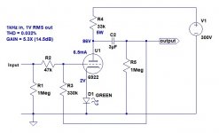
I've attached an example of a simple anode follower using a 6DJ8, arranged for 5.3X (14.5dB) gain. That is a simple triode stage with negative feedback plate to grid. R3 takes output signal and feeds it back to the grid, forming a voltage divider with R2, which defines how much negative feedback will be applied.
Using a single triode stage with no negative feedback, the gain is defined by the triode itself.
6N23P = ECC88 = 6DJ8 has mu of about 30
Real-life gain should be about 25X
That is 28dB gain
6N6P has mu of about 20
Real-life gain should be about 15X
That is 23.5dB gain
6V6-Triode has mu of about 10
Real-life gain should be about 7X
That is 17dB gain
12B4A has mu of about 8
Real-life gain should be about 6X
That is 15.5dB gain
As you can see, the anode follower (simple triode stage with plate-grid NFB applied) can reduce the 6DJ8's 28dB gain to about the same gain as a 12B4A (15dB), by applying 13dB of negative feedback (reducing the gain of the 6DJ8 by 10dB, or about 3.3X).
Attachments
Last edited:
With a circuit that uses NFB you can adjust the gain to your requirements.
I've attached an example of a simple anode follower using a 6DJ8, arranged for 5.3X (14.5dB) gain. That is a simple triode stage with negative feedback plate to grid. R3 takes output signal and feeds it back to the grid, forming a voltage divider with R2 (which defines how much negative feedback will be applied).
Using a single triode stage with no negative feedback, the gain is defined by the triode itself.
6N23P = ECC88 = 6DJ8 has mu of about 30
Real-life gain should be about 25X
That is 28dB gain
6N6P has mu of about 20
Real-life gain should be about 15X
That is 23.5dB gain
6V6-Triode has mu of about 10
Real-life gain should be about 7X
That is 17dB gain
12B4A has mu of about 8
Real-life gain should be about 6X
That is 15.5dB gain
This is interesting! thank you.
yes that is what I meant. output after the coupling cap. back to the grid..
Then I can get rid ot that dist. without having to use an extra tube. dont I?
Then I can get rid ot that dist. without having to use an extra tube. dont I?
Yes, NFB reduces THD.
However, this depends on the load the 6DJ8 has to drive. The plate-grid NFB appears as an additional load in parallel with the rp of the 6DJ8, in parallel with its plate load resistor (R4), in parallel with the output load resistor (R5), and in parallel with the input resistance of the load (your power amplifier). Normally you'd want to add a buffer (cathode follower or source follower) to the anode follower, to reduce the load on the triode. But in this case your load (your power amp) has a high input impedance of 1Meg ohms. That will help keep the 6DJ8 from getting 'loaded down', so yes, this particular circuit will reduce the THD of the 6DJ8 by almost 13dB as well as reducing its gain by that much.
To make the circuit work even better, you could put a cathode follower after the triode gain stage and take the output signal from after the output cap from the cathode follower. But you said you didn't want to use any followers, so I offered this simpler circuit as an example.
--
Yes. Its not that I dont want to use one, but..🙄
If its strictly neccessary I will.
I just thought that because I dont need to drive anything but the 1M input impedance power amp.. it would be ok without one.
How do I know if the load on the triode is too high?
I'm not sure what you mean by "If the load on the triode is too high".
If the amplifier really does present a load of 1M ohms, then I don't think you have to worry much about the triode stage being burdened by a heavy load. If you do the math of paralleling the various loads on the triode, you can figure out exactly what the load will be.
6DJ8 rp = 4k ohms (roughly)
That will work into a load of:
Rp = 33,000
R3 = 330,000
R5 = 1M
input R of amp = 1M
33k // 330k // 1M // 1M = 28.3k ohms
That's a light enough load on the 6DJ8. It should work fine.
--
Last edited:
Then you are back to something like the dynaco pas4, a u-follower/srpp configuration that has low dist AND low to very low output impedance.Yes. Its not that I dont want to use one, but..🙄
If its strictly neccessary I will.
I just thought that because I dont need to drive anything but the 1M input impedance power amp.. it would be ok without one.
How do I know if the load on the triode is too high?
At one 6922 per channel there is not much as cost efficient available.
I'm not sure what you mean by "If the load on the triode is too high".
If the amplifier really does present a load of 1M ohms, then I don't think you have to worry much about the triode stage being burdened by a heavy load. If you do the math of paralleling the various loads on the triode, you can figure out exactly what the load will be.
6DJ8 rp = 4k ohms (roughly)
That will work into a load of:
Rp = 33,000
R3 = 330,000
R5 = 1M
input R of amp = 1M
33k // 330k // 1M // 1M = 28.3k ohms
That's a light enough load on the 6DJ8. It should work fine.
--
Hello again. Thank you.
"If the load on the triode is too high", was in response to
"..to reduce the load on the triode"
I have also done the math. My question was indeed regarding those 28k.
How do I know if that load is too high or not for the triode.
That was my question.
Thank you!
I'm not sure what you mean by "If the load on the triode is too high".
If the amplifier really does present a load of 1M ohms, then I don't think you have to worry much about the triode stage being burdened by a heavy load. If you do the math of paralleling the various loads on the triode, you can figure out exactly what the load will be.
6DJ8 rp = 4k ohms (roughly)
That will work into a load of:
Rp = 33,000
R3 = 330,000
R5 = 1M
input R of amp = 1M
33k // 330k // 1M // 1M = 28.3k ohms
That's a light enough load on the 6DJ8. It should work fine.
--
Then you are back to something like the dynaco pas4, a u-follower/srpp configuration that has low dist AND low to very low output impedance.
At one 6922 per channel there is not much as cost efficient available.
Yes. Thats really an option. A common ac cathode follower like this
DIY 6922 / E88CC Tube preamp could be as well.
which pro's would have the u-follower over the latter?
Thanks!
Both will have some amplification, the u-follower has NFB to keep dist down ( that could be implemented on the other too)Yes. Its not that I dont want to use one, but..🙄
If its strictly neccessary I will.
I just thought that because I dont need to drive anything but the 1M input impedance power amp.. it would be ok without one.
How do I know if the load on the triode is too high?
It's a matter of taste , both has potential for good sound.
Hello everyone! I am trying to get the Merlin 3 valve phono PCB printed but it seems the bottom layer of the PCB is not visible in the manual. It can be seen here: http://www.valvewizard.co.uk/phono_pcb4.jpg
but not clearly. Anyone perhaps has a picture of it?
Thank you!
but not clearly. Anyone perhaps has a picture of it?
Thank you!

If you make a replica of this board i would like to sugest a few improvements ( i have built one of these )Hello everyone! I am trying to get the Merlin 3 valve phono PCB printed but it seems the bottom layer of the PCB is not visible in the manual. It can be seen here: http://www.valvewizard.co.uk/phono_pcb4.jpg
but not clearly. Anyone perhaps has a picture of it?
Thank you!
Make the input and output in the form of 5 mm ground + signal where one can mount either a mail pin connector
as often seen in computer boards or a screw mount ( connector ) or (pin mount )
Using pinmount has the benefit that the board may be removed without tools and crimped cables and connectors
are less prone to damage and/or loose wires.
Then make sure the ground and power connections are well formed and with a similar choice of connector(s)
- Home
- Amplifiers
- Tubes / Valves
- Merlin phono preamp + extra gain stage