Help me figure out the problem.
Most likely, a faulty device was connected to the input (or simply static electricity from a poor grounding).
In general, the digital input stopped working (2 of 5).
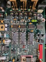
There are 5 inputs (+1 output) on the board, and each chip apparently serves two inputs. All I could do was ring the resistors at the input of the microcircuits, and apparently the signal from the connectors reaches the microcircuit through passive elements.
This is some kind of microcircuit marked 74HCU04D, and then another one 74HC4094N (D2151ME) after it.
Of course, I hoped that there was a fuse somewhere along the input, but there was none. I understand that it is most likely worth starting with these microcircuits, but which one?
Apparently it’s worth starting with the first one, since it’s most likely broken (but possible next one). Perhaps many people know this implementation of digital input and similar problems.
What are your guesses?
The photo shows the Meridian DSP series 5 (561/562/565/568).
Most likely, a faulty device was connected to the input (or simply static electricity from a poor grounding).
In general, the digital input stopped working (2 of 5).
There are 5 inputs (+1 output) on the board, and each chip apparently serves two inputs. All I could do was ring the resistors at the input of the microcircuits, and apparently the signal from the connectors reaches the microcircuit through passive elements.
This is some kind of microcircuit marked 74HCU04D, and then another one 74HC4094N (D2151ME) after it.
Of course, I hoped that there was a fuse somewhere along the input, but there was none. I understand that it is most likely worth starting with these microcircuits, but which one?
Apparently it’s worth starting with the first one, since it’s most likely broken (but possible next one). Perhaps many people know this implementation of digital input and similar problems.
What are your guesses?
The photo shows the Meridian DSP series 5 (561/562/565/568).
Attachments
Last edited:
Multimeter is available. It seems the most logical thing to replace 74HCU04D, since it is the first at the input and can withstand something like -0.5 to VCC + 0.5, which clearly could damage it.
Last edited:
What about the isolation baluns? Fatigue crack in the wire or a solder joint?
Besides, a 74HCU04D is what, an unbuffered hex inverter? Best to scope it first.
Besides, a 74HCU04D is what, an unbuffered hex inverter? Best to scope it first.
I see that the signal goes from the resistors immediately after the filter (coils and caps) to the legs of the microcircuit 74HCU04D (8-STAGE BUS REGISTER).
Judging by its current and voltage parameters at the input, any sneeze could kill it.
https://eu.mouser.com/datasheet/2/302/74HC_HCT4094-1148954.pdf
Judging by its current and voltage parameters at the input, any sneeze could kill it.
https://eu.mouser.com/datasheet/2/302/74HC_HCT4094-1148954.pdf
Last edited:
Okay. You can replace it if you want. Maybe that will fix it and maybe not. If not, then if you want to go about troubleshooting scientifically and methodically, then maybe we can help.
What is the dac worth anyway? What does a low-cost 100MHz (or better), 2-channel scope cost?
What is the dac worth anyway? What does a low-cost 100MHz (or better), 2-channel scope cost?
I agree with you. On the one hand, the chip costs less than $3, and it’s easy to replace it, unlike at least $150 for an oscilloscope. This is still the most obvious suspect.
I also understand that I can’t do without a good oscilloscope, but I’m afraid I’ll need it very rarely. I understand all the convenience of a multi-channel oscilloscope with good bandwidth, accuracy, and signal generators, but to check whether the microcircuit produces a signal of the desired (or at least similar) shape, a cheap thing should be enough. Probably I have to buy something inexpensive to check.
What also makes me think is that apparently this microcircuit serves two inputs, and it is precisely two that do not work, which clearly points to it.
So will wait new updates.
Last edited:
Not really, if we are talking about dac work. 100MHz is about the minumum. 200MHz or higher is better yet. Otherwise the square wave clock signals will look like sine waves, maybe very small sine waves if that....a cheap thing should be enough.
These are bog standard CMOS logic ICs; an inverter and a shift register. The parts are cheap (<$1 ea). If you have sufficient solder/desoldering skills and are used to working with larger SMD components, I would go ahead and change these. The 4094 in a PDIP-16 package could be a bit more difficult to find, though searching for CD74HC4094E shows that Digikey has these. I'm guessing that the photo you provided in the 1st post isn't your unit. The two chips to the left of the ones you marked are pretty crooked for a commercially produced unit and almost indicate someone has been in there.

No, this is my device... 74HCU04D look like they've already been replaced before me. But the input worked before that until I burned it.
So maybe I'm not the first to do the same 🙂
Although I have encountered situations where the breakdown passed through several microcircuits further, I still have hope that it stopped there. That's why I'll change it first.
Regarding 4094, it looks more massive and I hope it survived.
So maybe I'm not the first to do the same 🙂
Although I have encountered situations where the breakdown passed through several microcircuits further, I still have hope that it stopped there. That's why I'll change it first.
Regarding 4094, it looks more massive and I hope it survived.
Last edited:
It might be worth checking the supply to the 7404's. Pin 14 should be at 5 volt with pin 7 at zero volt (ground). Also check each input and output pin. For static inputs (not connected to anything) I would expect to see simple logic levels, whatever an input is (logic 1 or 0) the output should be the opposite. The 7404 is commonly used to clean up digital inputs in situations exactly like this.
There are six invertors in each package. Yours look as if they may have a resistor (feedback) from output to input to add hysteresis forming a Schmitt trigger and ensuring clean switching. Some in the package may be unused with the input tied high or low but the same rule applies, whatever is on the input should generate the opposite logic output.

There are six invertors in each package. Yours look as if they may have a resistor (feedback) from output to input to add hysteresis forming a Schmitt trigger and ensuring clean switching. Some in the package may be unused with the input tied high or low but the same rule applies, whatever is on the input should generate the opposite logic output.
Looks very simple. Does this mean that in my case only 2 inverters out of 6 are used. Because 3A-3Y and 6A-6Y are ringing from the resistors at the top front of the chip.
I don’t have the circuit, but if we assume that the others are not involved, then you can try to throw a jumper on the adjacent pair inverter without desoldering the microcircuit.
This makes me a little sad, since I see live contacts 3A-3Y and 6A-6Y (current passes), so the microcircuit may be working. Although this does not mean that it works normally.
In any case, I'm waiting for a new chip to replace it. I'll try to ring it again from different contacts.
I doubt many of the invertors are redundant tbh. Spare invertors may be used as buffers or used for other functions.
If you know you yourself did something/connected something/caused something to happen and this unit was in your possession and working up until that moment and then after you yourself did something and it failed then replacing the chips is probably the way forward.
If there is any other history to this then all bets are off 🙂
If you are not used to working with SMD then this might help although the resolution of the pictures isn't great:
https://www.diyaudio.com/community/...ow-to-do-it-without-specialised-tools.127924/
Yes, of course, it was something like a static discharge (or the case was poorly grounded or not grounded at all).
In general, I think that much more than the standard 0.5V went to the input.
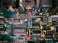
I also see nearby an absolutely identical loop of other inputs that work. So I still hope that this is a local problem with this chip.
In general, I think that much more than the standard 0.5V went to the input.
I also see nearby an absolutely identical loop of other inputs that work. So I still hope that this is a local problem with this chip.

Actually that's all. The device began to purr.
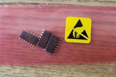
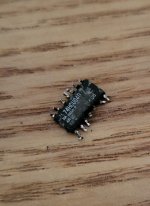
The only thing I want to say is hello to those who soldered this microcircuit.
It looks like it was welded and glued with epoxy resin. I bent the tweezers 20 times and finally removed it with pliers.
I also recommend reading this
https://www.diyaudio.com/community/threads/connecting-ungrounded-and-grounded-devices.414157/
If you want to preserve your equipment, then perform any switching not just with the device turned off, but with the fully unplugged socket.
Attachments

I'm pleased that is all it was 👍
Back in the day (TV's, VCR's etc) it was possible to draw an arc from an aerial downlead or Scart lead as it made/broke connection with the TV. Leakage from SMPS in the TV was to blame but remarkably we didn't seem to get any failures attributed to this. You could often read it on a meter as around half mains voltage and if you got hold of a lead in one hand and TV socket with the other you got a real belt off it but no current behind it.
Back in the day (TV's, VCR's etc) it was possible to draw an arc from an aerial downlead or Scart lead as it made/broke connection with the TV. Leakage from SMPS in the TV was to blame but remarkably we didn't seem to get any failures attributed to this. You could often read it on a meter as around half mains voltage and if you got hold of a lead in one hand and TV socket with the other you got a real belt off it but no current behind it.
- Home
- Source & Line
- Digital Line Level
- Meridian digital input fail