Hi Guys,
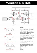
A friend of mine recently bought a Meridian 606 DAC. It goes, but has a rather serious fault; it clips when playing anything over 6dB in level. The output of the DAC IC (a SAA7350, unfortunately this 606 doesn't use a TDA1547) is undistorted and unclipped, so the fault appears to be within the output stage. The fault appears on both channels.
The first thing I checked were the power supplies, I found them present and correct. I then traced out the schematic and noted down the voltages and waveforms present. I'm not clued up enough on this sort of circuit to fix it myself. I understand how it works, but I don't understand why it has been made this way, nor why it isn't working. I suspect the DC servo is at fault, as it is one of the few items common to both channels (one half of the LF353 is used for each channel).
I have attached a picture (and PDF of that picture) showing the output stage, the waveforms on each node and the DC voltage component on each node. I traced the circuit from the circuit board, so please let me know if you think I've traced something wrong.
Any suggestions are appreciated, I would really like to fix this DAC.
Thanks,
Anton
Attachments
I suspect the DC servo is at fault, as it is one of the few items common to both channels (one half of the LF353 is used for each channel).
I think so too, servo opamp output is at 13V5 DC..a way to high. Also you have to protect J-fet opamp input with low leakage diodes.
It looks to me like it's hard against its rail, I doubt you'd get much more out of it from +/- 15V supplies.
I'm pretty sure there aren't any there. Remember, this is a Meridian DAC, I didn't design this.
Also you have to protect J-fet opamp input with low leakage diodes.
I'm pretty sure there aren't any there. Remember, this is a Meridian DAC, I didn't design this.
No ideas anyone?
What I don't understand is why it is clipping. I wouldn't have thought that the common mode voltage from the DAC would have been a big deal, and that if it was, that the clipping would be asymmetrical.
The way the the LF353 DC servo is driving as close as it can to its negative rail seems wrong to, or is that the way this type of DC servo should be operating?
At first step I would remove the offset servo LF353. What happens?No ideas anyone?
What I don't understand is why it is clipping. I wouldn't have thought that the common mode voltage from the DAC would have been a big deal, and that if it was, that the clipping would be asymmetrical.
The way the the LF353 DC servo is driving as close as it can to its negative rail seems wrong to, or is that the way this type of DC servo should be operating?
and what is the function of the 4 k-Ohm resistor from output to the inverted input of the second NE5534? This topology is curious for me.
Additional have a look to the pages 18 until 20 about
http://www.analog.com/static/imported-files/data_sheets/AD1955.pdf
This topology is more easy to understand (at least for me).
If you use this topology, this clipping behaviour is blown away - and you will find nearly "rail-to-rail" character.
Last edited:
I resolved this problem, the DAC works fine now. It turns out that the entire circuit that I posted, labouriously traced from a four layer board, was functioning perfectly well. The problem lay downstream of it, with some components whose function I had thought to be trivial. Lesson learned.
The confusing thing about troubleshooting this circuit was that because the output is fed back into both inputs it's really hard to to tell whether the fault is at the input or output.
The confusing thing about troubleshooting this circuit was that because the output is fed back into both inputs it's really hard to to tell whether the fault is at the input or output.
- Status
- Not open for further replies.