OK, I learned a couple of things
-this is a sub amp. I was supplying a 1K signal - no drive. When I dropped it to 100hz and set my scope up using differential inputs I found a drive signal. Drive signal drops out if I sweep up to about 400hz or higher.
Is this wave ok? Is it safe to put the output fet's in with the 10V difference on the hi side between the G and S. or will that remedy when the feedback loop initiates.
Attachments
Differential would be ch1 - ch2.
What are the red and yellow supposed to be?
The bottom of the drive waveform should be at ground.
What are the red and yellow supposed to be?
The bottom of the drive waveform should be at ground.
I was using the procedures you listed in pic.
Wouldn't Ch1 + Ch2 inverted be the same as Ch1 - Ch2?
The red and yellow I assume are the indivdual Ch1 and Ch2 before the scope does the math. I do not seem to be able to get them to go away, but there is probably a way to do it.
Is there a better way to scope the drive signal on output fets that have close to rail voltage on the gate? Where would I get a grd reference?
Attachments

1 + an inverted 2 is 1-2.
When it's right, you should be able to place both probes on any point and get a straight line trace on the display's reference line.
When it's right, you should be able to place both probes on any point and get a straight line trace on the display's reference line.
That is exactly what I get when the leads are on a common point. Straight line at the reference line.
What might cause the drive signal to swing to -10v instead of 0v. It is consistent on hi and lo side.
What might cause the drive signal to swing to -10v instead of 0v. It is consistent on hi and lo side.
For N-channel FETs, the trace will swing from ground to +10v.
For P-channel FETs, the trace will swing from ground to -10v.
For P-channel FETs, the trace will swing from ground to -10v.


Touch the tab/drain of the PS FETs with:
Ch1 probe
Ch2 probe
Both probes
3 images. Leave the scope in differential mode for all. Set the scope to 10us and 10v/div.
Ch1 probe
Ch2 probe
Both probes
3 images. Leave the scope in differential mode for all. Set the scope to 10us and 10v/div.
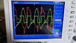
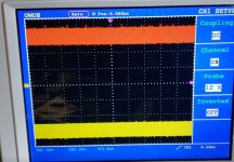
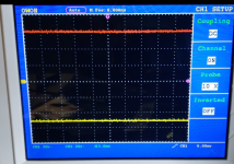
The green trace on the first two are right. I don't know why the yellow trace is there on the second. I don't know what 3 is showing unless the scope isn't triggering properly. In differential mode, you should have only one trace showing. Read the manual to see how you make that happen.
Is there a way to invert the second channel and then add the signals like you would on an analog scope?
Do you have another scope?
Is there a way to invert the second channel and then add the signals like you would on an analog scope?
Do you have another scope?
The third is both probes together and the green trace is flat on the reference line. Isn't that correct?
I guess you have to disregard the red and yellow traces and just look at the green. I read the manual and there is no way to shut off the red an yellow traces.
Anyway the driver board seems off:
The rails are stable at +/- 61v
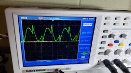
The first 3 photos are with no audio input.
1st photo P channel gates are at 50v and N channel are at -60v
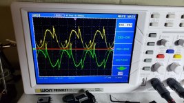
2nd photo a glitch for a micro second
3rd photo now P channel gates are at 60v and N Channel at -50v.
A 10v shift on both hi and lo gate voltages. I can get this to repeat.
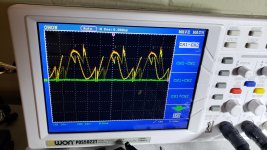
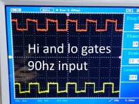
4th photo Applied a 90hz input to the RCA's. This pic details the gate drives when the voltages are in either of the above 2 conditions.
P channel gate is swinging from 50v to 70v
N channel gate is swinging -50v to -70v
I guess you have to disregard the red and yellow traces and just look at the green. I read the manual and there is no way to shut off the red an yellow traces.
Anyway the driver board seems off:
The rails are stable at +/- 61v
The first 3 photos are with no audio input.
1st photo P channel gates are at 50v and N channel are at -60v
2nd photo a glitch for a micro second
3rd photo now P channel gates are at 60v and N Channel at -50v.
A 10v shift on both hi and lo gate voltages. I can get this to repeat.
4th photo Applied a 90hz input to the RCA's. This pic details the gate drives when the voltages are in either of the above 2 conditions.
P channel gate is swinging from 50v to 70v
N channel gate is swinging -50v to -70v
Attachments

The drive is likely OK.
When the scope is properly set up in differential mode, it will work normally with the non-inverted probe. When you need to use it in differential mode, all you have to do is pick up the inverted channel probe and use it in conjunction with the other probe.
There are several things that you and anyone trying to repair amps should do. No one will take this advice but I'll post it anyway.
Learn to properly use your scope. If it takes 12 hours of intense study, do it. Once you learn it, you won't have to struggle with it again.
The same goes for op-amps and the basic circuits that they're used in. Take as long as it takes, using as many resources as it takes. You should be able to calculate the output of any simple op-amp circuit is given the components in the circuit and the input voltages.
And again with the power supply driver ICs like the TL494. I'd bet that a million or more of these have been replaced for absolutely no reason over the years because people were too lazy to put in the time to learn how they work.
Read through datasheets for various ICs. You won't remember everything but you will pick up useful bits and pieces that will prove useful.
With all of these, take notes.
All of this saves time and money in the long run.
- Home
- General Interest
- Car Audio
- Memphis PR1-1000 Zener ZD1 value?