I recieved a Memphis today from a friend of mine. I know that it has been repaired before. Powers up fine and draws around 2.8amps of current at idle. So I started to test the amplifier and pushed a 50hrtz signal into the amplifier. It audible from the output transistors? Seems like more on one side. This is all I have done this far. I'll test through the op amp section. Some of the legs on the chip are not even soldered in?
Attachments
Card unsoldered? But I see that those legs go to nothing and unused.
Attachments

Last edited:
A few of the outputstage are reaching over 105°f. Still checking around the board. And there are so many mismatched transistors date codes in here. None are shorted as far as I can tell in curcuit.
Last edited:
U won't beleive this one, resistors at the RCA inputs were not even soldered in properly, or not at all on one side of them the amplifier is working perfectly now.
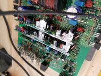
Yes. There should be a thick piece of thermal gap pad between those and the bottom cover. All of this is to help cool those drivers.
There is perry, pads and thermal paste. Most hard and dried up, so should I apply some fresh Dow Corning to the drivers
That's what I did and I'll reapply a nice layer to all the transistors and clamp it down and bench test it. Thanks.
I’m sorry to hijack your thread, I was wondering if you could do me a huge favor? I need a few parts identified from your Memphis 2000D if you don’t mind?
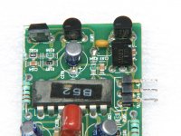
I’ve attached a picture of the removable board that I’m working on and I’ve circled the 4 x missing parts that I need identified. I recently received this amp to repair and a few parts were missing, including 2 of the 4 removable boards!
Luckily, I have spare boards from other Memphis amps that I use only for parts. I appreciate the help.
Attachments

I would greatly appreciate that and I agree with you, this site has been a priceless solution to many problems that I've run across! Thanks again for posting those components. If there is anything I can help you with in the future, please let me know.
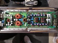
To add some reassurance about the output cards in this amp running pretty darn warm during normal operation, Perry was dead on as usual with his answer. I believe I've asked the same question in the past.
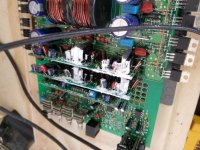
Both the 2000D and st-1500, Memphis Audio's older "studio modesl", share the same 3 card configuration in the output section and one card in the power supply section. The cards look almost identical in layout as well.
As Perry mentioned, the output transistors/drivers come heavily coated In thermal paste, with rubber-like thermal pads in-between the drivers. Like you, I was originally very concerned about the amount of heat generated from these removable boards. It's just designed that way and seems to work great for these amps.
If you have any other questions, please start your own thread.
The two 'U' components are TL431/kia431 type regulators.
The transistor on the right, you can read. I don't have a good photo of the one on the left but I believe that it's a KTC1027. The circuit is similar to the JBL BP1200.1, You may be able to use that diagram for the value of the capacitor.
http://www.bcae1.com/temp/bp1200p1_sm.pdf
Attachments
- Status
- Not open for further replies.
- Home
- General Interest
- Car Audio
- Memphis mojo 16-MC2000D output trouble.