I'm repairing an older Memphis Audio amp, 16-2000D. Replaced all output transistors, all rail capacitors, and all .04 ohm protection resistors, it now powers on and out of protection.
The op amps are all reading -14.7 and +8.5 when at idle, Shouldn't these numbers match or at least be closer in value?
I'm also concerned about the amount of heat coming from both audio output cards, they are too hot to touch after idling for only 5 min.
Do these issues point to a particular component that I overlooked during the repair? Voltage regulator? Thanks for any advice
Attachments
The regulators are generally closer. Sometimes the problem is using the primary ground instead of the secondary ground as the reference.
Post a photo of the inside of the amp if no one answers your other questions.
Post a photo of the inside of the amp if no one answers your other questions.
They use L7x15 regulators Confirm that the input to the regulators is sufficient to allow the regulator to produce rated voltage.
The drivers are supposed to have thick thermal gap pads that sink the heat to the bottom cover. It's normal for them to run hot.
Side note, in the similar amps that I've seen, the 9640s used 0.04 ohm resistors. The 640s used 0.02 ohm resistors.
The drivers are supposed to have thick thermal gap pads that sink the heat to the bottom cover. It's normal for them to run hot.
Side note, in the similar amps that I've seen, the 9640s used 0.04 ohm resistors. The 640s used 0.02 ohm resistors.
When I first opened the amp, it had L7812 and L7912 being used. They appear to be original parts but maybe the regulators are suppose to be L7815/L7915?
Can you confirm which regulators should be used? Thanks
Can you confirm which regulators should be used? Thanks
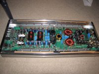
I removed all 3 PCB cards in the audio section and the amp powers on beautifully.
I installed the card closest to the RCA jacks, see attached images, and the large resistor in front of the regulator begins to smoke, it also appears that the amp's drawing too much current.
Would this be an issue with that particular card or something else in the circuit that connects once the card is installed? Thanks
Attachments
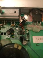
I measured 32 ohms between the ground and output of the 7812, the regulator closest to the smoking resistor.
I measured, what appears to be, a capacitor charging when I measure between the ground and output pin of the 7912.
Does this mean that the 7812 has blown out again during my last bench test? Thanks Perry
I measured, what appears to be, a capacitor charging when I measure between the ground and output pin of the 7912.
Does this mean that the 7812 has blown out again during my last bench test? Thanks Perry
Desolder the output leg (or remove the regulator completely if the board is out of the heatsink) and recheck the resistance.
With the regulator removed from the board, I'm reading 32 ohms between the ground and output pads on the board.
I'm reading 25.9K ohms when measuring the actual ground and output pins on the regulator.
I'm reading 25.9K ohms when measuring the actual ground and output pins on the regulator.
When I remove the card from the board and measure the resistance between the regulator's ground and output pads, I'm reading 5.4K ohms
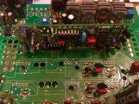
That could indicate that you have a defective component on the audio PWM board or a solder bridge on that board. A solder bridge could be between the main board and the plastic part of the connector. Use your meter to confirm that you don't read 0 ohms (or near 0 ohms) between any adjacent pins on that board.
What's a good substitute for a KIA 431, I believe this is a shunt resistor? I found this from mouser, would it be an acceptable substitute?
http://www.mouser.com/ProductDetail...GAEpiMZZMuBck1X%2b7j9fGCdUvo4ZwvaNfX9wKSc5Jw=
http://www.mouser.com/ProductDetail...GAEpiMZZMuBck1X%2b7j9fGCdUvo4ZwvaNfX9wKSc5Jw=
I measured .2 ohms between the outer legs of the shunt transistor while it was still in circuit. Once I removed it and remeasured, it seems to be fine.
Thought this might be my issue but I'm back to not having a clue. If I can't find any bad components on the The PWM board, my next area of examination should be the area around the op amps, correct?
Thought this might be my issue but I'm back to not having a clue. If I can't find any bad components on the The PWM board, my next area of examination should be the area around the op amps, correct?
- Status
- Not open for further replies.
- Home
- General Interest
- Car Audio
- Memphis 16-2000D repair