Are you sure that the scope was set to 0.2v/div?
If you set it to 0.5v/div and touch it to the B+ terminal of the power supply, does the trace go off of the top of the display?
Was there an input signal or not?
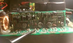
You can look at the solder joints and compare it to the other driver board to determine if anything has been replaced.
If you set it to 0.5v/div and touch it to the B+ terminal of the power supply, does the trace go off of the top of the display?
Was there an input signal or not?
You can look at the solder joints and compare it to the other driver board to determine if anything has been replaced.
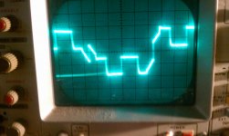
yes its set to 0.2 volts/div
If you set it to 0.5v/div and touch it to the B+ terminal of the power supply, does the trace go off of the top of the display? no doesnt move.
Was there an input signal or not? no
the resistors in the picture look like one end was taken up then resolderd to the to of the board.
If you set it to 0.5v/div and touch it to the B+ terminal of the power supply, does the trace go off of the top of the display? no doesnt move.
Was there an input signal or not? no
the resistors in the picture look like one end was taken up then resolderd to the to of the board.
There seems to be something very wrong with the scope or the way you're using it. This needs to be addressed before we can use any scope images.
Go to the oscilloscope page of the site, find the 'best initial settings' and set your scope as described there. After reading the text, read the questions under the text and make sure that you can answer all of them.
Set the scope to 0.5v/div and touch the probe to the B+ terminal of your power supply. The trace should disappear beyond the top of the display. Set it to 5v/div. The trace should deflect ~2.5 divisions. Confirm that that's what you see. If not, VERY specifically explain what you see.
Now that you have the scope working properly, with no input signal, check the signal on the gates for the audio FETs.
Set the timebase to 5us
Set the vertical amp to 5v/div
Set the coupling to AC (one of the few instances where you'll set it to AC coupling)
Do all of the gates have a square wave?
Set the timebase to 5us
Set the vertical amp to 5v/div
Set the coupling to AC (one of the few instances where you'll set it to AC coupling)
Do all of the gates have a square wave?
- Status
- This old topic is closed. If you want to reopen this topic, contact a moderator using the "Report Post" button.
- Home
- General Interest
- Car Audio
- memphis 1000d