Next is to review this circuit. To better understand its design and find out key parts to perform possible upgrade, I built a LTSpice model and simulate the circuit. See the attached. What I found:
1. The input caps 19, 28, 64, 70 are necessary for differential operation.
2. The INPUT-(GND) cap has no signal between both ends, just doing DC bias. Thus those caps are really not critical. On my board, those caps are 0.68uF and different type than the INPUT+ input caps that used 1uF Mylar caps. I think that may be the reason.
3. At the power up, the outputs has Volts of DC offset on the output, I guess that would be the reason I heard low frequency noise from my speaker but that ran away during long time listening.
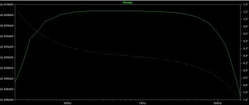
4. The JFET Drain resistor was critical for amplification and balance. From my simulation, changed that to 100 will get much better balance on the output. I suggestion to use high precision resistors or best matched there.
(Sim_1G_res_100DR.jpg)
5. I don't understand 100K plate resistor purpose. You can see on the attached simulation the output offset is much better when that changed to 1G ohms (assumed open). (Sim_1G_res.jpg)
Please share your thoughts.
1. The input caps 19, 28, 64, 70 are necessary for differential operation.
2. The INPUT-(GND) cap has no signal between both ends, just doing DC bias. Thus those caps are really not critical. On my board, those caps are 0.68uF and different type than the INPUT+ input caps that used 1uF Mylar caps. I think that may be the reason.
3. At the power up, the outputs has Volts of DC offset on the output, I guess that would be the reason I heard low frequency noise from my speaker but that ran away during long time listening.
4. The JFET Drain resistor was critical for amplification and balance. From my simulation, changed that to 100 will get much better balance on the output. I suggestion to use high precision resistors or best matched there.
(Sim_1G_res_100DR.jpg)
5. I don't understand 100K plate resistor purpose. You can see on the attached simulation the output offset is much better when that changed to 1G ohms (assumed open). (Sim_1G_res.jpg)
Please share your thoughts.
Attachments
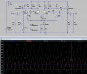
I dug into this circuit and tuned some parts values to find out possible upgrade options. I realized Melos design has to work with a input capacitor because it can't tolerate any input offset. They tried to convert the single ended to balance but this approach had some challenges. Through simulations, I found it was hard to make the Hot and Cold outputs exactly match. The best I can do is 0.06dB. I was wrong in the previous comment, this circuit has feedback, the 475K is sampling the output current and feedback to its input. To have minimum change to the circuit, I have the parts values as shown in the attached picture that gave best simulation results.
Attachments

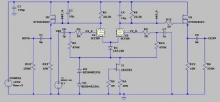
The critical part in this design is the drain resistor of JFET. I will put a trimmer potentiometer there so I am able to tune that value for the best result. I will share some measurement when I got chance. Simulation depends on many conditions may not be very accurate.
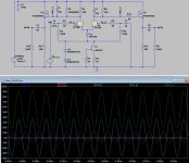
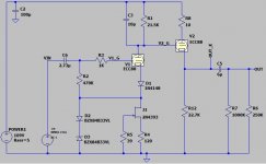
The 2nd modification option is to make it single ended. My power amplifier has only SE input for there is no benefit to do XLR especially there was question in its balance design in my opinion. To convert it to SE, I will use one part of 6922 for output buffer instead of the questionable output MOSFET IRF510. I will not worry about the balance performance, save one pair of output capacitors that I plan to invest more expensive parts there. 6922 performance is better than any of MOSFETs as far as I know.
Here is the circuit modify and simulation result:
Here is the circuit modify and simulation result:
Attachments
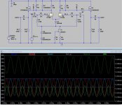
My 3rd option is to improve this SE circuit by a common tube preamp design. Remove the switching diode replace with a bias resistor, remove the feedback 475K resistor as I won't see any advantage from that tiny feedback.
The great advantage of this upgrade is the circuit tolerates more than 2V of input offset. That means I don't need input capacitors! Not only save money, but also improve the sound because direct connection has the least distortion per my understanding. Move over, this circuit can go stable state quicker (Sim_SE_Mod33.jpg) than Melos circuit (Sim_balanced_Mod15.jpg). See circuit and simulation below that added 2V input offset:
The great advantage of this upgrade is the circuit tolerates more than 2V of input offset. That means I don't need input capacitors! Not only save money, but also improve the sound because direct connection has the least distortion per my understanding. Move over, this circuit can go stable state quicker (Sim_SE_Mod33.jpg) than Melos circuit (Sim_balanced_Mod15.jpg). See circuit and simulation below that added 2V input offset:
Attachments


Last edited:
Albert, great work. A total redesign....I am slowly agreeing on the whole balanced output of this pre - I always thought it was their clever balanced design implementation that made this pre sound so good. I have since came across an Audible Illusions 2A cheap locally with same 6922 with other half doing buffer, and outputs in SE and sounded as good if not better than the Melos, so it may not have been attributable to the balance out...
I plan to build something eventually, but the 6922 buffer vs IRF MOSFet buffer, do they both get you down to that same low output impedance? I do not remember what Melos claimed, but it was very low...
I plan to build something eventually, but the 6922 buffer vs IRF MOSFet buffer, do they both get you down to that same low output impedance? I do not remember what Melos claimed, but it was very low...
John, If tune this pre-amp carefully it will give good balanced output. In my simulation, the best I made is 22.408dB(P) vs 22.488dB(N) that human ear will never distinguish that difference. I will do some test to check if it really like my simulation result.
When I working on this reverse engineering, I kept checking what other brands doing, especially the designs of Audio Research, C-J, Audio Note products. I found Melos balanced design was pretty unique, most other brands would do the same input buffer but only output one phase, not balanced. I think it was challenging to make a good balance. Audio Research makes the balance output from its balance input with trimmer to tune the P-N bias. I only simulated ideal condition, not included all the drift impacts, like temp, offset, gain etc. However, human ear may not be sensitive in P-N unbalance. It could be great sound but potential distortion in measurement.
About 6922 vs IRF510, I won't see any difference in output impedance that was defined by the drain resistor, 10K. I don't think Power MOSFET was a good idea in this application, because their major application was to output high current. To do that, the MOSFET was implemented big size die so input capacitance was high that will be side effect of signal fidelity.
Last edited:
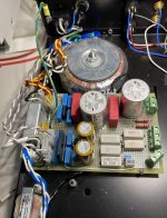
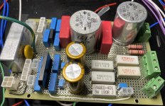
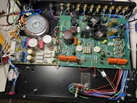
Power supply Board build
The original SHA was cabling and soldering for every connections, which was hard to get anything out to change or service. I don't think there was enough filtering for High voltage supply.
I just designed and built a bread board to offload some power supply parts from Amp board and added additional filter, especially added EMI filter. I also added connectors so all power connections can be unplugged. Here is the schematic:
Attachments

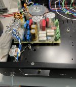
Holy smokes!! The led regulators on far right side of amp board are still functioning / in circuit?
The Low voltage regulators are still at their original locations on the Amp board. I powered up yesterday, everything worked!
Attachments
Last edited:
Here is something I measured:
1. The filtered High Voltage input is ~140V.
2. The regulated High voltage output is ~104V.
3. The dropout over the 100ohm resistor is ~7V, that indicates the ideal load without tube is ~7mA
4. The dropout over TL783 is ~22V, that was too much! So only 7mA already heat that chip much.
5. The outputs of filtered low voltages are ~+/-14V without tube load.
6. The outputs of regulated low voltages are ~+/-6.5V.
7. Dropout over LM317/LM337 is ~7V. Again, that is too much, especially those are unnecessary heat dissipation.
My comment and questions for Melos on Amp board power design:
1. For High voltage regulation, the 4 Darlington/LED circuit are sharing ~10V of dropout voltage, not sure if there was other purpose. If adding some small caps that will help regulation but Melos didn't. I don't see any purpose that type of circuit has to be used. I would rather adding another TL783 if I want to share power dissipation in regulation circuit. If you could see any benefit please share comment here.
2. I won't see any problem to apply higher voltage to tube plate. It would increase the amplification circuit power dissipation but also increase the dynamic range of line stage. At least that is not energy waste than that 100 ohm resistor and 4 darlingtons. So I plan to increase the high voltage to 125V from the current 104V. I will need to change other parts values after the plate voltage change but I can handle that.
3. The 2 tube filaments are powered by -6.5V and Headphone output (assume average GND level). The current of 2 filament is 365mA*2=730mA. It makes +/-6.5V load unbalance a lot. The power dissipation of LM337 (assume 12V Vin when loaded tube) is (12-6.5)*0.73=4W. Too much and uneven!
4. Using headphone to power the filament should be fine in theory but I highly not prefer to keep that. So I plan to modify the circuit to power one tube filament with 6.5V-GND, and another GND-(-6.5V).
5. I hope I could add another winding on the power transformer to create ~7VAC then regulate to 6.3VDC only for filament and increase the headphone circuit supply voltage to ~+/-12V. That should be the best option but way too complex. I would reserve that for the future mod.
Some corrections on my previous comment:
1. In power supply High voltage circuit, the dropout over 100ohm without tube was 7V, and 8V with tube inserted in. That is: The current was 70mA (NOT 7mA) in ideal condition and 80mA with tube.
2. TL783 power dissipation was 22V*0.08=1.76W
3. The output impedance is mainly contributed by the SOURCE resistor of IRF510, ~10K in Melos design.
4. The VDS of IRF510 is 100V but is OK with the drain voltage over 100V because the source is not grounded but connected to the output.
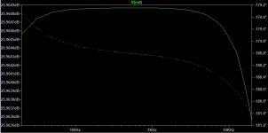
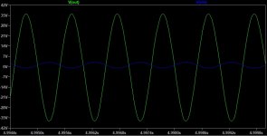
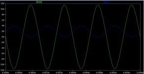
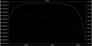
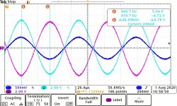
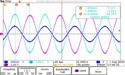
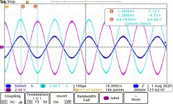
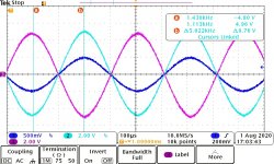
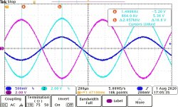
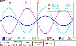
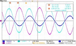
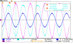
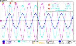
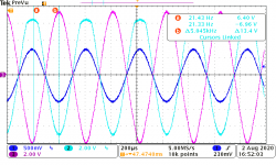
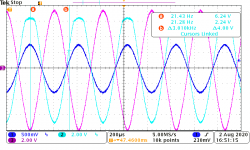
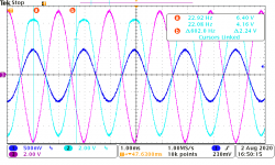
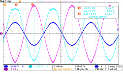
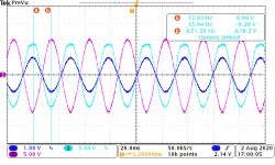
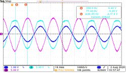
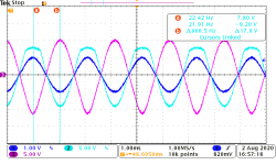
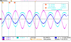
I think this will be more interesting. I did some scopeshot on the current Melos amp board. It was actually not bad, not like my simulation result. It only has a little attenuation and offset shift on very ends of frequency, ~20Hz and 19KHz. See attached:
Blue: Input
Cyan: Output Non-inverted
magenta: Output Inverted
Blue: Input
Cyan: Output Non-inverted
magenta: Output Inverted
Attachments
-
 LS_20KHz.jpg144.3 KB · Views: 57
 -
 LS_15KHz.jpg147.9 KB · Views: 38
 -
 LS_10KHz.jpg156.6 KB · Views: 41
 -
 LS_5KHz.jpg159.9 KB · Views: 45
 -
 LS_2K5Hz.jpg145.8 KB · Views: 45
 -
 LS_1KHz.jpg143.7 KB · Views: 97
 -
 LS_500Hz.jpg143.9 KB · Views: 107
 -
 LS_50Hz.jpg142.5 KB · Views: 111
 -
 LS_18Hz.jpg142.3 KB · Views: 143
Last edited:
80ma thru both tubes? Approx 20ma thru each triode? Isnt that quite high on a 6922?
I never liked the idea of the photoresistor - just a nightmare waiting to happen, looks like you replaced with a dual pot. I would have done same.
So actual results better than sim, but because of you mods / additions? You are measuring inverted / non inverted at the Balanced outs? They were not working previously with Photoresistor input board (you said only single ended outputs from XLR pins?)
The frequency deltas look off on some of your graphs (I may be reading wrong)??
Also, make the four input caps (yellow pair and green pair) same value and maybe that frequency & voltage differential will converge?
EDIT: - Ok, forgot that the HV also feeds the IRF510 follower- that's why 80ma - how much thru tube?
Last edited:
- The current is 70mA without tube 80mA with tubes so both tubes consume 10mA, 5mA per each. The current through IRF510 must be less then 5mA. Those 10KOhm resistors at 4 darlington outputs consumes lots of power but doing nothing.
- I didn't input through any potentiometer, but directly applied to input of Amp board, Piont A and B, C.
- My 6922 model was copied from Ayumi SPICE models that found from another thread:
Vacuum Tube SPICE Models
Yes, I measured at the balance outputs.
I was wrong before, both XLR outputs work. They didn't measure good because the output relay hold the signal to ground.
- The frequency was approximate. You may double the number from screenshot to get frequency because I only measured half period to get the top and bottom amplitude.
- I am not sure changing the ground input caps could improve anything. For the balance design from single ended input Melos may have done good enough. The both frequency ends distortion may be caused by tube, output caps, or IRF510? not sure...
I saw some pictures other people modified the linestage with pricey caps on 4 inputs.
Last edited:
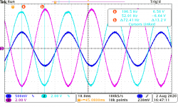
Done more scope measurement today, and realized the problems. During the input amplitude increasing, the output distortion was more and more significant, which match the some simulation results. See attached scopeshot with 1.5V input.
Attachments
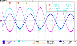
Here is worse situation with 2V input voltage, the output was terrible. What is that mean? The SHA Line stage can only be used with small input and its dynamic range was limited. You may not use the full CD players output as their output was about 2.8V. The signal has to be cut off by half or even more by attenuator (photo or physical potentiometer) to apply to the amplifier board, then amplify ~10X. However, if you get differential output, its amplification fact should be high enough. I think that is why John like her XLR so much! 🙂
It is not to challenge Melox. Her design was to create headphone amp, small signal should be great enough. Its line stage might not be designed to compete ARC, or C-J.
These results gave me more confidence to modify SHA GOLD to Single ended line-stage.😀
It is not to challenge Melox. Her design was to create headphone amp, small signal should be great enough. Its line stage might not be designed to compete ARC, or C-J.
These results gave me more confidence to modify SHA GOLD to Single ended line-stage.😀
Attachments

- Home
- Amplifiers
- Tubes / Valves
- Melos SHA GOLD Line Stage