Ok I have acquired a mc368-b150 amplifier and have done a few things with it to share. I haven't really found a lot of info on it so I will start. First of all i ordered this amplifier from china to work with 120vac what i got was a 115/230v version with a 230v power cord but amp was set for 115 vac with appropriate fuse 5 amp. i contacted ming da via email and was told that it will work fine on the 123 vac i have at my receptacle at home. I have a yaqin mc100b that i run at exactly 110v with an apc voltage regulator as its rated 110v ac +/- 10% and 123 vac is out of its upper limit. ming da says the mc 386 b-150 amp i have actually has power transformer wound for 120vac with +/- 10%. I am currently running it at my house 123 vac power. so i open the amp and check a few things. first of all the bias of the amp was a little high so i rebiased the amp for my house power which by the way is suppose to be .4 to .45 vdc across the 10 ohm cathode resistor between ground and pin 8 of the KT150 tube. B+ is too high for my current fluke meter which is rated for 600 v it wont read it so im assuming its above 600v. the 6sn7 and 6sl7 voltages are within specs. and finally the heater voltage was sitting at 6.9v.the heater voltage is rectified via full wave bridge and filtered with large capacitor. so i added a .1 ohm resistor in series with the ac feeding the bridge rectifier and voltage is now 6.3 to 6.4 volts varies with load fluctuations.Also did some power testing using 2 200 watt 4 ohm dummy load resistors and feeding 400 hz signal into the amp with function generator. pushed the amp to signal just before clipping i calculate from rms value and dummy resistor right at 125 watts rms per channel not the 150 watts advertised but still pretty respectable amount of power. also linearity to the point of clipping looks good and balanced. all i have is a oscope and function generator so didn't do any distortion testing. Signal on oscope looked good didn't see any crossover distortion or ringing with a quick audio sweep of my function generator. OK now the sound what about how does it sound? well... I am running some jbl 2800 speakers and i use a fisher eq890 equalizer and at first the amp didn't have very detailed bass but sounded good even running it with flat input sounded decent. after about 3 days of running it and rebiasing it it has opened up and sounds pretty darn good. bass finally came in and even my daughter came out to my garage and said damn that sounds good. she never does that lol. I have pictures of the internals but not sure if i can post them yet as this is my first ever post. I am an electronics tech with a CET and was an electronics instructor for 8 years and have 30 years in. any questions please feel free to ask. as of now i'm not going to do any more with the amp but listen to it. i will post more info on it as it comes Thanks
I don't understand what changed to get the bass notes that at first instance you said not to have. Changes in voltages doesn't change frequency response. Biasing affects distortion but not frequency coverage. Also, tubes are rated in ±10% in their heaters ratings, so you didn't need to tune them. In certain instances, tubes run better with a little high filament voltage as the electron cloud is bigger, and better protection on the cathode is obtained. In other instances, lower voltage is desired, as little noise is taken from them.
reply
I never said changing the voltage changed the bass notes also it got bass notes before bias but i rechecked several days later and had to readjust some due to the tubes being brand new. sometimes new tubes need a little time on them to get them to settle or open up and they do start sounding better. the heater voltage was fine at 6.9 volts but tend to last longer at their rated 6.3 volts the KT150 is an expensive tube at about $100 us dollars a tube i rather them last.
I never said changing the voltage changed the bass notes also it got bass notes before bias but i rechecked several days later and had to readjust some due to the tubes being brand new. sometimes new tubes need a little time on them to get them to settle or open up and they do start sounding better. the heater voltage was fine at 6.9 volts but tend to last longer at their rated 6.3 volts the KT150 is an expensive tube at about $100 us dollars a tube i rather them last.
I would suggest knocking the line voltage down to 110V for this amp. Your measurements for the heater voltage suggest that is the design center for the PT.
reply
i've tried that i plugged into my variac and got 6.3 heater voltage at 113 vac. I'm gonna bite the bullet on this one and let it run at 123 vac. transformers are slightly warm but not hot. ming da says its ok to run it at this voltage so well see how long it lasts.
i've tried that i plugged into my variac and got 6.3 heater voltage at 113 vac. I'm gonna bite the bullet on this one and let it run at 123 vac. transformers are slightly warm but not hot. ming da says its ok to run it at this voltage so well see how long it lasts.
sometimes new tubes need a little time on them to get them to settle or open up and they do start sounding better...
Tubes drift their properties along their life, but this is the first time I read that varies in the such a manner as to be "audible".
my tubes now have at least 100+ hrs on them and yes it sounds better. sorry about this being the first time you hear this being an engineer and all. YAWN!
reply
I am referring to the power tubes I have 2 tube hifi amplifiers and both sounded marginal out the box. and the bias does tend to drift in the first hrs on power tubes. i'm not saying bias is affecting the sound on my amplifier. on my amplifiers after some hrs they stabilize(the power tubes). maybe just my ears, but does tend to sound a lot better after about 100 hrs or so to me. I know what you are getting at. i was thinking the same thing saying BS! use to think tube sounded real midrangy etc. its just resistors, capacitors, and valves, voltage, and current, and coils what can change? simple answer is i'm not really sure. i did read an article about changes in electronics at a microscopic level especially in capacitors, and resistors, electrons forming paths etc. some people speculate that this contributes to a change, like a break in period of new electronics.
I am referring to the power tubes I have 2 tube hifi amplifiers and both sounded marginal out the box. and the bias does tend to drift in the first hrs on power tubes. i'm not saying bias is affecting the sound on my amplifier. on my amplifiers after some hrs they stabilize(the power tubes). maybe just my ears, but does tend to sound a lot better after about 100 hrs or so to me. I know what you are getting at. i was thinking the same thing saying BS! use to think tube sounded real midrangy etc. its just resistors, capacitors, and valves, voltage, and current, and coils what can change? simple answer is i'm not really sure. i did read an article about changes in electronics at a microscopic level especially in capacitors, and resistors, electrons forming paths etc. some people speculate that this contributes to a change, like a break in period of new electronics.
my tubes now have at least 100+ hrs on them and yes it sounds better. sorry about this being the first time you hear this being an engineer and all. YAWN!
That was a mite disrespectful. Well, more than a mite, actually.
Bias doesn't depend on tube characteristics itself, as it is a value imposed from outside of the tube. If bias varies, it depends on a drift in resistor(s) or potentiometer(s), not in tube itself, except when potential contact bias using 10MΩ resistors from grid to cathode and no cathode bias, grounded directly. The behavior of the tube does depend on bias, but it is difficult to believe that change in tube characteristic tilt the frequency/amplitude diagram of an amplifier. Moreover, it depend practically 100% on passive component values like transformers, resistors, capacitors and (Eventually) inductors. All this, unless you are using tube of so bad quality that their interelectrode capacitance varies tremendously with hours of usage. Again, I never had seen such a circumstance.
Schematic for the mingda
Been awhile since ive replied mean no disrespect also have enclosed a schematic from mingda for anyone who needs it also been running this amp at 123 vac all year amp doing fine just put a new set of kt 150's, 6sn7's and 6sl7's as i put a lot of hrs. on it. also added 1 amp slow blow fuse on ac side of b+ winding of power transformer between transformer and rectifier. you will notice on schematic its on the dc b+. mine did not have one and i experimented with a fuse there and it blows pretty easy. better to put it were i have it now at ac winding of B+ before rectifier. 6sl7 and 6sn7 heaters are elevated the kt150's are not. i put bourns trimmer pots for bias the ones mingda puts in are kind of squirly. kind of a pain to bias this amp as it has extremely high B+ IN the chassis and you will have to open it lean on its side i use a 2X4 under the right side transformers to prop up so it doesn't fall.
Been awhile since ive replied mean no disrespect also have enclosed a schematic from mingda for anyone who needs it also been running this amp at 123 vac all year amp doing fine just put a new set of kt 150's, 6sn7's and 6sl7's as i put a lot of hrs. on it. also added 1 amp slow blow fuse on ac side of b+ winding of power transformer between transformer and rectifier. you will notice on schematic its on the dc b+. mine did not have one and i experimented with a fuse there and it blows pretty easy. better to put it were i have it now at ac winding of B+ before rectifier. 6sl7 and 6sn7 heaters are elevated the kt150's are not. i put bourns trimmer pots for bias the ones mingda puts in are kind of squirly. kind of a pain to bias this amp as it has extremely high B+ IN the chassis and you will have to open it lean on its side i use a 2X4 under the right side transformers to prop up so it doesn't fall.
Attachments
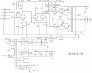
That amp is not suitably designed for the KT-150 and you may find that the tubes destroy themselves from the high grid leak resistance. The 220K grid leak resistors need to be brought down to the value specified in the datasheets, and likely the coupling caps should be adjusted to maintain the same time constants.
reply
Hey thanks for the info. also if you notice on the schematic the bias filter capacitors for B-1 and B-2 look to be backwards the 10uF 250V caps on the schematic.
Hey thanks for the info. also if you notice on the schematic the bias filter capacitors for B-1 and B-2 look to be backwards the 10uF 250V caps on the schematic.
ok fixed bias limit 51kohm for the KT150 i calculate a time constant of 103.4ms with the values in the amp (coupling cap X grid leak resistor) to reduce the grid leak resistor to say 50k that gives me roughly a 2uF coupling cap im assuming which should be fine to couple the input signal though a little large. does this seem right or am i missing something here. I'm not exactly a vacuum tube expert any info appreciated I would like to fix this right. Thanks
reply
Hi The input tubes i am using are JJ brand 6SL7 and the phase splitters are electro harmonix 6SN7. I also have not made any more modification to the amp. I contacted Ming DA and they had advised against adjusting grid leak resistors. I do use my amp a good bit and it works fine im not too worried about it at this time. When i first got the amp I listened to it a lot. Now i listen to my Yaqin mc-100b more often as im driving a smaller set of speakers at normal listening volume. The mingda is quite powerful and The speakers I have on them are quite sensitive and are loud at the initial volume the amp will set itself to and finding i have to turn it down after it warms up. Also the JJ and electro-harmonix tube sound really good to me. One of the onion shaped ps vane 6sn7's that came with the amp originally became microphonic. So i changed them and the preamp tubes. I use electro harmonix tubes in my Yaqin amp as well and quite pleased with the performance as well as the price. I have tried several different tubes in the Yaqin and find electro harmonix and jj tubes to be the best bang for the buck. I do also use PS vane hifi KT88's which are pretty decent as well. The KT150 are pretty expensive as I have already bought a new matched set for the mingda. but the old ones were fine even with a lot of hrs. on them.
Hi The input tubes i am using are JJ brand 6SL7 and the phase splitters are electro harmonix 6SN7. I also have not made any more modification to the amp. I contacted Ming DA and they had advised against adjusting grid leak resistors. I do use my amp a good bit and it works fine im not too worried about it at this time. When i first got the amp I listened to it a lot. Now i listen to my Yaqin mc-100b more often as im driving a smaller set of speakers at normal listening volume. The mingda is quite powerful and The speakers I have on them are quite sensitive and are loud at the initial volume the amp will set itself to and finding i have to turn it down after it warms up. Also the JJ and electro-harmonix tube sound really good to me. One of the onion shaped ps vane 6sn7's that came with the amp originally became microphonic. So i changed them and the preamp tubes. I use electro harmonix tubes in my Yaqin amp as well and quite pleased with the performance as well as the price. I have tried several different tubes in the Yaqin and find electro harmonix and jj tubes to be the best bang for the buck. I do also use PS vane hifi KT88's which are pretty decent as well. The KT150 are pretty expensive as I have already bought a new matched set for the mingda. but the old ones were fine even with a lot of hrs. on them.
- Home
- Amplifiers
- Tubes / Valves
- Mei xing MC368-B150 amplifier