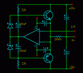
Just looking for comments on this circuit I dreamed up for a medium-fi amp suitable for voice, as in public address system etc. Actually, when I make it up I'll take some measurements and see just how hi or low the "fi" is.
The most interesting feature as far as I am concerned is the output stage biasing. At standstill, the bases have approx 1mA, maybe even less, the idea is to have a very low standing collector current. The opamp is to flatten out any crossover distortion, but in contrast to some other underbiased ccts, there is no slack when the base drive would normally have to swing very quickly from one base to another during the crossover period. As soon as the opamp output moves away from the outgoing base it is immediately pushing on the incoming base because the capacitors are charged to Vbe. There may be a little wiggle in the main output voltage, but not a great big notch, and so the opamp has a much better chance of straightening it all out.
The schottky diodes make sure the opamp does not drift more than 0.2v outside the base voltage window. Ordinary diodes would be ok though. They are not for thermal feedback, in fact they are pointing the wrong way for that. The base emitter junctions determine the bias voltage, not the diode forward voltage drop - here they are usually reverse biased in fact.
The opamp supply rails ride up and down on the main amp output so the demands on the opamp slew rate, gain, common mode range, output voltage swing etc are minimal. In fact, there is no limit on the opamp output swing; you can have it go + / - 100v if you like! And the slew rate capability would be off the planet.
I expect the opamp would need a small local feedback cap to keep it under control at very high frequencies.
There it is, then. Whaddya think?
GP.
Attachments
Well, I tried this thing without the opamp and just feed a raw transformer coupled sinewave into where the opamp output would have gone, and put about 100uA into the bases. It works ok for about 1 second during which time the rectification effect of each BE junction allows each base cap to discharge a bit each half cycle and not recharge! So as the caps run down and the xover distortion returns. Tried putting a 2200uF from one base to the other but this only slowed down the inevitable. Hmmm... Gotta do some more thinking on this.
GP.
GP.
- Status
- Not open for further replies.
