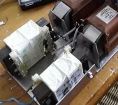
Just received some new parts as follows. I have 2 of each (for monoblocks) and thus am able to swap to see if a specific part is the issue.
The filament transformer (4V for an Aa tube) + 2A LC filament supply works as designed. spot on. no problems.
However, filament transformer (20V for GM 70 tube) + 3A LC filament supply produces a significant mechanical hum/vibration from the filament transformer. The GM70 tube is drawing 2.88A current (spec is 3A). The GM70 is measuring 19Vdc (spec is 19-20Vdc). So, I swapped transformers. Still same issue. I swapped LC filament supply. Still same issue. I swapped tubes. Same issue.
Then, instead of using the 3A LC, I tried a Coleman V9 regulator. This worked fine. Just a slight mechanical hum from the filament transformers, but nothing worth discussing. So, it appears that the LC is causing the filament transformer to hum, yet the transformer is rated for 3A. Any thoughts on this?
Here is the LC design:

FYI: Once I get the filament transformer mechanical hum problem fixed, I will be adding another choke. This will give a nicely supplied LCL. I am comparing the LCL to the LC + Coleman solution. Should be fun once the mechanical hum is fixed.
Custom Monolith Magnetics Filament Transformer with multiple secondaries
2A Intact Audio LC filament supply (made for multiple tubes with filament current < 2A)
3A Intact Audio LC filament supply (made specifically for GM70)
The filament transformer (4V for an Aa tube) + 2A LC filament supply works as designed. spot on. no problems.
However, filament transformer (20V for GM 70 tube) + 3A LC filament supply produces a significant mechanical hum/vibration from the filament transformer. The GM70 tube is drawing 2.88A current (spec is 3A). The GM70 is measuring 19Vdc (spec is 19-20Vdc). So, I swapped transformers. Still same issue. I swapped LC filament supply. Still same issue. I swapped tubes. Same issue.
Then, instead of using the 3A LC, I tried a Coleman V9 regulator. This worked fine. Just a slight mechanical hum from the filament transformers, but nothing worth discussing. So, it appears that the LC is causing the filament transformer to hum, yet the transformer is rated for 3A. Any thoughts on this?
Here is the LC design:
FYI: Once I get the filament transformer mechanical hum problem fixed, I will be adding another choke. This will give a nicely supplied LCL. I am comparing the LCL to the LC + Coleman solution. Should be fun once the mechanical hum is fixed.
It's not L-C, but CMC-C filtration.
CMC (Common Mode Choke) is effective against common mode disturbation coming from secondary, but does not behave like "real" high current choke.
CMC (Common Mode Choke) is effective against common mode disturbation coming from secondary, but does not behave like "real" high current choke.
No.
Static current (filament) + first smoothing capacitor (I think several mF) charging pulses is the cause: this sum excitation exceeds transformer capabilities.
Rule of thumb: the secondary current capacity MUST be at least double/triple than static load current.
p.s.: I usually use four-five times greater wattage transformer than load (for DC filament).
Last edited:
Bela - How would I test to determine what the filament transformer wattage is built? It was spec'd for 3A non-overrated steady state. But, I would like to measure the wattage. Not sure how to do this.
If you know the core sizes (and manufacturer/core type), the estimated power capacity is known from datasheet.
BTW 3A means: 3A with resistive load.
If you use full wave rectification, large first capacitor, this capacity is enough .... for 1.5A DC load.
Sample:

BTW 3A means: 3A with resistive load.
If you use full wave rectification, large first capacitor, this capacity is enough .... for 1.5A DC load.
Sample:
Bela is of course right. The transformer power calculation always requires a good margin, to avoid voltage sag, overheating and hum. Remember filaments run 100% load, full time!
GM70: Range of Ifil = 2.7-3.3A so assume 3.3A. This means 6.5A rms (AC) in the transformer! A 60% margin is the minimum, and 100% is not overdoing it. Look for 10-12A. If your choke is really allowing choke-input operation, you will still need something like 5-6A.
BTW, If the CM choke in your drawing is the high-inductance Lundahl type, it may cause rising impedance at some frequencies. This is not a good feed for low-noise regulators, and may degrade the sound of my new V9. It is best to test the V9 with the standard CRC supply given in the manual. (This is a divergence from earlier versions that may have been helped by LC Raw DC feeds made with simple 10mH chokes).
Hello,
If you '' study '' the datasheet of Lundahl power transformers you will see that the given current rating is for choke input and if it is capacitor input the current rating is nearly 40 % lower. With a proper choke input ( enough mH) your transformer is probably still to small. You could check what happens if you use a BIG power resistor to achieve 2A current being drawn instead of the GM70..
Rod just told us that the new V9 works better with CRC but skipping the input choke will probably make life much harder for the power transformer.
greetings, Eduard
P.s I used Lundahl filament choke and rather small power transformer for my VT25A heaters
Attachments
Hello Eduard! It's possible that some LC Raw DC designs will prove to be fine with the V9. but they are very variable, and it is difficult to recommend them without testing. But the impedance must not rise much, at any frequency, to maintain the full performance of the V9.Rod just told us that the new V9 works better with CRC
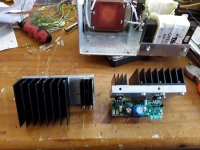
I do like your heat-spreader, BTW.
Hello,
I just checked the specs of the parts i used
20 volt 2,4 A transformer.
LL2733 wired like pictured in the first post. Total DCR 3,4 ohm and 544mH choke rated for 1,25A but Lundahl always uses a big safety margin. AND because AC voltage across the choke is very small compared to the maximum ( 120 volts) current can be higher i was told.
I think that there wont be a problematic impedance rise because the Lundahls are build in a special way AND i am not using the new V9. Maybe i will if a better sound is guaranteed and brexit doesnt make things to expensive.
Greetings, eduard
High current capacitor charge pulses make transformer windings rattle. If no deep impregnation or potting is done on the coils, they will usually buzz. Even varnished only coils can result in the whole coil buzzing if it's loosely coupled on the core.
To test if this version, you could load the transformer with the equivalent load without any rectification - just connect a resistor across the secondary that results in the same RMS current. If buzzing stops, then you will know windings are the culprit.
If buzzing occurs even during an unloaded transformer, then the core is the noise culprit.
Just received some new parts as follows. I have 2 of each (for monoblocks) and thus am able to swap to see if a specific part is the issue.
Custom Monolith Magnetics Filament Transformer with multiple secondaries2A Intact Audio LC filament supply (made for multiple tubes with filament current < 2A)3A Intact Audio LC filament supply (made specifically for GM70)
The filament transformer (4V for an Aa tube) + 2A LC filament supply works as designed. spot on. no problems.
However, filament transformer (20V for GM 70 tube) + 3A LC filament supply produces a significant mechanical hum/vibration from the filament transformer. The GM70 tube is drawing 2.88A current (spec is 3A). The GM70 is measuring 19Vdc (spec is 19-20Vdc). So, I swapped transformers. Still same issue. I swapped LC filament supply. Still same issue. I swapped tubes. Same issue.
Then, instead of using the 3A LC, I tried a Coleman V9 regulator. This worked fine. Just a slight mechanical hum from the filament transformers, but nothing worth discussing. So, it appears that the LC is causing the filament transformer to hum, yet the transformer is rated for 3A. Any thoughts on this?
Here is the LC design:
View attachment 1052717
FYI: Once I get the filament transformer mechanical hum problem fixed, I will be adding another choke. This will give a nicely supplied LCL. I am comparing the LCL to the LC + Coleman solution. Should be fun once the mechanical hum is fixed.
Hi Euro21, your CMC is drawn with the dots on opposite sides of the inductors.If you know the core sizes (and manufacturer/core type), the estimated power capacity is known from datasheet.
BTW 3A means: 3A with resistive load.
If you use full wave rectification, large first capacitor, this capacity is enough .... for 1.5A DC load.
Sample:
View attachment 1052755
I have seen some manufacturers (like kemet) drawn CMC with the dots on the same side
for common mode chokes. Some manufacturers (like TI) don't even draw the dots !
But this from this LL1673 datasheet
http://www.lundahl.se/wp-content/uploads/datasheets/1673.pdf
put the dots on opposite sides for "improved common mode rejection",
and no DC (single) choke is suggested.
Can you comment on those? I am here to learn and perhaps correct misconceptions that I might have.
If you connect CMC "dots on the same side", the "input" current flows in phase on both coils, so core magnetizing (due to the static current), and common mode noise cancellation not working. It's a simple choke with two coils and large flux.
If you connect it "dots on opposite sides", the static currents excitations extinguished (no flux), and common mode noises also extinguish each other (differential mode).
It's working as (common mode) noise cancellation device.
p.s.
The built PSU contains D=30mm core CMC and LARGE SU amorphous core choke (wound 1mm CU wire).
Last edited:
Euro21, thank you for your comments.
I look up a book by Henry Ott: Noise Reduction Techniques in Electronic Systems. 2nd Edition.
On page 96, Low-Frequency Analysis of Common-Mode Choke. The chokes are drawn with the dots on the same side.
"A transformer can be used as a common-mode choke (also called a longitudinal choke, neutralizing transformer ...).
A transformer connected in this manner presents a low impedance to the signal current and allows dc coupling.
To any common mode noise current, however, the transformer is a high impedance."
Is it true that CMC noise suppression can be viewed either as isolation (high impedance) and flux cancellation ?
So the dots do not matter ?????
- Home
- Amplifiers
- Tubes / Valves
- Mechanical vibration on new filament transformer