I'm using .27R resistors to drop heater voltage from 6.3v to 5v, but when I measure with my DMM they measure higher, around .5R. I also tried putting 4 in series and got 1.4R, which is better but still a bit high. Is that just the tolerance of my DMM? The markings on the resistors are correct.
What does your DMM say when you press the leads firmly together? Most say non-Zero. Lead and fuse resistance.
Does it really matter? Are your heater voltages coming out right? (Since this may be a rectifier, disconnect the high voltage AC so your meter is not exposed to huge DC.)
Does it really matter? Are your heater voltages coming out right? (Since this may be a rectifier, disconnect the high voltage AC so your meter is not exposed to huge DC.)
Perhaps the wires you use for measuring have 0.3 or 0.4 Ohm resistance? Just hold the plus and minis wire together. Do you measure more than 0 Ohm? Then that’s just your wiring. This value you have to substract form your measured values.
Regards, Gerrit
Regards, Gerrit
In the interim I tried it out, no fireworks, not that I expected anything.
As an aside, I've gone to using a remote AC power switch while taking measurements and testing. I don't want to have to touch anything if something is going wrong.
I checked the resistance of the wiring of the meter and it is indeed .3 to .4. Thanks.
As an aside, I've gone to using a remote AC power switch while taking measurements and testing. I don't want to have to touch anything if something is going wrong.
I checked the resistance of the wiring of the meter and it is indeed .3 to .4. Thanks.
Last edited:
4-Terminal Resistance Measurement for the Poor
Low Cost Constant Current Solution for Low Resistance Measurements
Ever wonder how you could make accurate measurements of small resistance’s common in audio or power transformer windings? An ordinary Volt-Ohm-Meter (VOM) or Digital Multimeter (DMM) does a poor job. Your meters leads & contact resistance’s become a large part of the result. And the one Ohm mark on your analogue meter doesn’t leave much room to guesstimate the result.
For these kinds of measurements the 4-terminal method provides good results. But you will need some kind of Constant Current Source (CCS) with which to drive the Device Under Test (DUT). The test current from the CCS is applied to the DUT leads while a voltmeter reads the result on these same DUT leads. That way meter lead & contact resistances are eliminated. Accuracy of the result is insured.
A single VOM or DMM are all the measurement equipment required. The meter should have a low voltage scale, say one volt FS or less. That is now commonly available on low cost DMM’s.
I used a 12 volt automotive battery as my source. But any 12 volt battery of sufficient capacity would work OK. If the battery has been on charge it should be left for a few hours to stabilize.
The CCS is nothing more than the widely available automotive 1157 bulb. The bulb has two filaments, so two measurement ranges are possible. A 5 Amp fuse in the battery lead is also a good idea.
The meter is first set to its 10 amp scale. Then connect the meter, 12 volt battery, fuse, 1157 bulb & DUT all in series. The meter will indicate the total current thru the circuit. Under normal conditions the 1157 bulb will dissipate more than 20 watts. That is one reason I chose the bulb rather then looking for an equivalent 50 watt resister.
The meter is then disconnected & set to measure volts on a low voltage range. The circuit above is then reconnected as before without the ammeter in place. However the current will be altered only slightly from that measured since the ammeter voltage drop including its leads is only about 200 mv out of the 12 volts, less than 2%. Now connect the meter leads (set to volts) to the DUT leads. Measure the resulting voltage on the DUT leads & apply Ohm’s Law.
The 1157 bulbs large heater will apply about 2 Amps to the DUT. The small heater of about 0.5 Amp can be used on DUT windings of higher resistance. The other reason I chose an incandescent bulb rather than a power resister is for its dynamic resistance at its operating point in this application. While the large heater has a dynamic resistance of more than 10 ohms at 12 volts the resistor would still be about 5.5 ohms for these conditions. That helps to keep the test current constant while changing meter leads.
I built a much more elegant CCS in 1969 for doing these 4-terminal tests. But that is another story. You can read about it in AudioXpress July 2001.
Attachments
PRR presented the right “rhetorical question”, … is the voltage coming out right? IF 'yes', then the accuracy (or in this case inaccuracy) of low-value resistance measure doesn't matter one whittle. Trust the markings; as an old designer, I learned LONG ago to trust the markings.
Unless, of course, the parts are very old, of odd providence, recycled from other-equipment teardown, or having emitted smoke at some point recently.
⋅-⋅-⋅ Just saying, ⋅-⋅-⋅
⋅-=≡ GoatGuy ✓ ≡=-⋅
Unless, of course, the parts are very old, of odd providence, recycled from other-equipment teardown, or having emitted smoke at some point recently.
⋅-⋅-⋅ Just saying, ⋅-⋅-⋅
⋅-=≡ GoatGuy ✓ ≡=-⋅
I build amplifiers that need to use series resistance in the filament circuit.
My mains power varies from 117V to 123V, center of 120VAC.
I start with a resistor that should give the correct filament voltage with 120VAC power.
After the amp is wired, I check the voltage across the filaments, and adjust the resistance if needed.
By the way, the resistor provides an automatic soft start on the filament(s).
"The hardest thing in electronics is stuffing all the smoke back in"
Zacster, I do not know if this info will help you or not. Better DVM meters have a Relative button on them. The Relative maybe abbreviated as Rel. If you meter has this function, short the leads together tightly until you see the lowest reading displayed on the lowest ohms setting and then pres the Rel button and the meter will zero out the display. Thus, eliminating the resistance of the leads and fuse assembly. Now you can get a more accurate measurement. Remember good connections are a must when making extremely low resistance measurements. If you meter does not have a Rel button, all you can do as far as trying to better understand low resistances is to short the leads together on the lowest ohms scale and see how low a reading you can get (again, reading is of the leads and internal fuse). Then measure the resistor of interest and deduct the resistance of the leads and fuse to understand the value measured. Good luck... Mickeystan
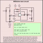
JHStewart has a decent recommendation. Updated a wee bit, the 'other way' is to cobble together an op-amp to make a 100× millivolt DC amplifier. Then, with a 10 Ω series resistor, and a 1.5 volt battery, one measures the millivolt difference voltage.
You could cobble all that together in a few minutes with an ancient 741 op amp (or any newer one) a resistor a 9 volt battery for the op-amp and a 1.5 volt battery for the sort-of-current-source.
All works out mathematically.
Attached is the diagram.
And some formulæ…
You could cobble all that together in a few minutes with an ancient 741 op amp (or any newer one) a resistor a 9 volt battery for the op-amp and a 1.5 volt battery for the sort-of-current-source.
All works out mathematically.
Attached is the diagram.
And some formulæ…
Attachments
Last edited:
Something like a 10 Amp constant current low voltage supply, OP amp control element, shunt and and triple EF works well for sub 0.02R.
1 Amp supply would similarly work well for 0.2R range (allowing for the "old" standard 1999 scaled digital meters, with appropriate shunt)
1 Amp supply would similarly work well for 0.2R range (allowing for the "old" standard 1999 scaled digital meters, with appropriate shunt)
You are all confusing me with someone that knows what they are doing! I decided I'd just trust the markings, since I had two different types both reading the same with the same markings and all brand new. And then the wire resistance also read to be the difference too.
When I put it all together and measured the original 6.3v though it measured 6.8v, so maybe I'll need to tweak anyway. It could be the mains power being high. The amp has worked for years the way it is so I'm not too worried, but I do want the 5v that I'm trying to get to really be 5v fully loaded.
Thanks for the advice.
The chief advantage of using a circuit such as the above … and 'committing it' to a little project box is that it is endlessly useful in the future, and only requires keying in a bit of math on a calculator to figure a mΩ value.
The calculation can be printed and affixed to the box… always nice. A DPDT on-off switch saves the batteries. Perhaps another DPDT switch changes 'ranges', by changing the gain of the op-amp from 100× to 10×. Again… awfully useful.
I just threw one together with a TL015CP (Texas Instruments, JFet input, 60¢/ea), and tested with a 150 mΩ resistor. Output was 2.33 volts. After measuring the 1.5 source and the resistors, keying in … calculated out to 147 mΩ. Using a $9.95 el-cheapo pocket 3½ digit multimeter. From now-defunct Radio Shack.
⋅-⋅-⋅ Just saying, ⋅-⋅-⋅
⋅-=≡ GoatGuy ✓ ≡=-⋅
^A cheap accessible idea.
Apologies to the OP, I figured I'd try and explain the resistance bridge I use at work as I havent a sketch to hand, but a picture is 1000 words.
A simple solution like the above is probably quicker to build and set up.
Apologies to the OP, I figured I'd try and explain the resistance bridge I use at work as I havent a sketch to hand, but a picture is 1000 words.
A simple solution like the above is probably quicker to build and set up.
^A cheap accessible idea.
Apologies to the OP, I figured I'd try and explain the resistance bridge I use at work as I haven't a sketch to hand, but a picture is 1000 words.
A simple solution like the above is probably quicker to build and set up.
Thanks. The really cool thing is, since the 'device reading' is entirely dependent on the measured values of the resistors and the 1.5 volt supply, just setting up a tiny spreadsheet with cells for the values … allows ANY reasonable values to still produce perfectly useful results.
In my case, before I tore down the circuit for another project 'on fire', I substituted in a 150 Ω resistor for the drawn 220 Ω and a 18 kΩ one for the 22 kΩ, and a 22 Ω DUT side one (for the 10 Ω) as well. Measured 'em all to 3 sig-figs on the cheapo multimeter, plugged them in, and got exactly the same 147 mΩ result. Ain't math a wonderful thing!
⋅-⋅-⋅ Just saying, ⋅-⋅-⋅
⋅-=≡ GoatGuy ✓ ≡=-⋅
No apologies needed.
And what is preventing me from trying out my 300B in this amp is super glue. I don't have any on hand and all the stores are closed. Maybe I'll check the Walgreens tomorrow since the pharmacies are still open. It is needed to hold the socket adapter together.
And what is preventing me from trying out my 300B in this amp is super glue. I don't have any on hand and all the stores are closed. Maybe I'll check the Walgreens tomorrow since the pharmacies are still open. It is needed to hold the socket adapter together.
To measure a low resistance accurately you can also use a Wheatstone Bridge. This consists of four resistors including the resistance under test. These are connected with Rs and Rt in series with the end points connected to a standard resistance wire firmly affixed to a wooden board. Current flows from one end of the resistance wire to the other and also through Rs and Rt. To make a measurement a metal slider is used. This is connected to a milliammeter (null indicator). One end is connected between Rs and Rt and the other to the metallic slider. The slider position is slowly changed until the milliammeter reads zero. This happens when the voltage at the midpoint between Rs and Rt and the point of contact of the slider are equal.
The theory is straightforward. If the length of the wire is L and the position of the slider is at x, and assuming the currents in both arms are i and j, we can write:
Very Important Note:
Rt is the test resistance and x is the length of wire on the same side of the test resistance.
The theory is straightforward. If the length of the wire is L and the position of the slider is at x, and assuming the currents in both arms are i and j, we can write:
Code:
Rt.i/(Rs.i) = x.j/((L-x).j)

=> Rt/Rs = x/(L - x)
=> Rt = Rs.x/(L - x)
Very Important Note:
Rt is the test resistance and x is the length of wire on the same side of the test resistance.
Actual last-measured values
R₁ = 21.3 Ω
V₁ = 1.44 V
R₃ = 18,600 Ω
R₄ = 151 Ω
V OUT = 1.23 V measured
∴ DUT = 0.148 Ω
as calculated in formula. Close enough! GGV₁ = 1.44 V
R₃ = 18,600 Ω
R₄ = 151 Ω
V OUT = 1.23 V measured
∴ DUT = 0.148 Ω
To measure a low resistance accurately you can also use a Wheatstone Bridge. This consists of four resistors including the resistance under test. These are connected with Rs and Rt in series with the end points connected to a standard resistance wire firmly affixed to a wooden board. Current flows from one end of the resistance wire to the other and also through Rs and Rt. To make a measurement a metal slider is used. This is connected to a milliammeter (null indicator). One end is connected between Rs and Rt and the other to the metallic slider. The slider position is slowly changed until the milliammeter reads zero. This happens when the voltage at the midpoint between Rs and Rt and the point of contact of the slider are equal.
The theory is straightforward. If the length of the wire is L and the position of the slider is at x, and assuming the currents in both arms are i and j, we can write:
Code:Rt.i/(Rs.i) = x.j/((L-x).j) ⇒ Rt/Rs = x/(L - x) ⇒ Rt = Rs.x/(L - x)
Very Important Note:
Rt is the test resistance and x is the length of wire on the same side of the test resistance.
Ah the fine smell of metrology equipment … and methods, and math.
I grew up SO long ago, that building a Whetstone Bridge was a standard part of our High School physics laboratory plan. Fun stuff, that.
However, given now we all have trivial access to reasonably accurate 3½ or 4½ digit pocket multimeters, to precision op-amps for under a buck, and the 'maths' (if you took a university-level op-amp/design class) to do what I did … then my silly little design can be cobbled together in 5 minutes or so, and produce results immediately.
The math took another 5 minutes.
Plugged into an Excel spreadsheet … bada-bam-bada-boom. Done. Someday, I'll commit the thing to a project box, and hunt down 'sweet resistors' (or 10 turn variable trim-pots), so that the math is even easier, in terms of nice round numbers.
One could go all crazy and do an Arduino project of course.
But half way between that and the Whetstone bridge is … a pocket DVM, a few resistors, an op amp, and some common batteries. On a buck-a-go plugboard.
I'm trying, begrudgingly, to take KISS into the 2020's.
LOL!
⋅-=≡ GoatGuy ✓ ≡=-⋅
OOOOpssss, it broke! Pull another one... No more strings, sorry, string puller.
A ridiculous post from a ridiculously named user. Maybe, they eat with goats and defecate like them. OOOOpsssss, severe dehydration may work. Do you get yourself milked as well? Yes, sure, you get milked... taxes!
A ridiculous post from a ridiculously named user. Maybe, they eat with goats and defecate like them. OOOOpsssss, severe dehydration may work. Do you get yourself milked as well? Yes, sure, you get milked... taxes!
Last edited:
4-Terminal Measurements Using a CC Supply
The attached article describes the CC Supply I built shortly after the beginning of time (1969) to solve my problems measuring low ohms & non-linear devices. Still works great, I used it again just a couple of weeks ago.🙂
There are several examples of real measurements on a transformer, diodes, silicon, germaium & LEDs & so on. And an NTC.
Attachments
- Home
- Amplifiers
- Tubes / Valves
- Measuring very low value (.27R) resistors?