The measurement with pot didn't corroborate those figures but that's part of my question. How or where does the "effective rp" manifest?
Are you sure that your measurements were done properly? Michael's "500 Ohm" estimate was simply based on 1/gm, I don't think he ever actually measure it though...
. . . . . . . .
The likely outcome for output impedance is that it will be low, but rather nonlinear as the feedback ratio depends on things like the pentode anode impedance. . . . . . .
Well, you are right. I didn't have a lot of time tonight so just ran three frequencies at four input levels each.
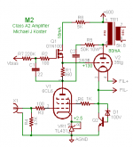
The setup was to short the input at the 6CL6 driver, RMS meter across 10R resistor in series with the plate, RMS meter across the 35T plate to cathode, and signal generator into a small amplifier driving the output transformer secondary.
The gist of it is effective rp for the 35T (not output impedance of the amplifier) measures as:
@50 Hz. ≈ 2K17
@100 Hz. ≈ 1K3
@1 KHz. ≈ 850Ω
I guess it will be safe to assume that at 10K it will be lower still but I don't know how much. There'll be a leveling out somewhere.
The result makes me wonder about the linearity of this sort of circuit. It measured with a pretty steep bass roll-off somewhere around 70Hz though you don't notice it so much when listening. I'll look more tomorrow.
I don't know why you are seeing such strong frequency dependence. Could it be the meters?
By "nonlinear" I meant that the impedance would change with signal level.
By "nonlinear" I meant that the impedance would change with signal level.
Well, they're both good RMS meters. Fluke and Tek.
Could it be the RC feedback circuit? Doing a quick calculator just now gets the graph below.
Could it be the RC feedback circuit? Doing a quick calculator just now gets the graph below.
Attachments
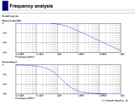
As I expected, the plots show things changing at subsonic frequencies but should be constant across the audio band. Still unclear why you are measuring a change in mid-band where nothing much should be changing in the circuit. What is the bandwidth of your meters?
For the past couple of weeks I've managed to do some tests on the circuit but the results vary, both with method and with one of the methods with level of input signal. In order to get a useful perspective on the data (lots of it) so I can sift it out before posting I need to better understand the meaning of the terms for feedback quantity.
As far as I know, feedback is typically quantified in dB but I've noticed when people are talking about Schade feedback it's usually in terms of percent.
One of the tests was to do comparative measurements of signal voltages across the OT primary and the 50K Rfdbk at a range of frequencies and the Vrms across the two were effectively the same. If I understand it correctly, this indicates there is 100% feedback. Please correct me if this is wrong.
In his posts , Michael Koster calculates that 100% feedback will reduce the 35T’s rp to 1/GM which at this operating point would ballpark it around 500 Ohms. This is what I need to confirm, as the figure tallies with only one of the test methods used and I’d like to figure out what I need to learn next in order to eliminate the erroneous results.
I'd appreciate the help and thanks if you can spare it.
Attachments
The feedback fraction is often quoted in percent or simply as a decimal fraction. 100% would yield unity gain; less if your gain block doesn't have 'infinite' gain like an op-amp.
Feedback magnitude is generally quoted in dB, which is the ratio of voltage gain between open-loop and closed-loop conditions. This tutorial might be helpful: Negative Feedback and Negative Feedback Systems
Feedback magnitude is generally quoted in dB, which is the ratio of voltage gain between open-loop and closed-loop conditions. This tutorial might be helpful: Negative Feedback and Negative Feedback Systems
Last edited:
Thanks for the link. It's a good site and I'll read it through, though my question still remains - If the signal voltage across the feedback resistor R5 is equal to that across the output transformer primary, does that constitute 100% feedback ?
No, that could be 0% feedback. 100% feedback would be full signal voltage at both ends of R5, due to the anode impedance at the first stage being infinite.
I believe we have to analyze this as a shunt feedback system with the summing node at V1 anode. AC voltage across R5 gives us the feedback signal current into that node from V2 anode. Forward signal current arrives via V1 anode resistance, so it's not as easy to measure. B (feedback fraction) would be the ratio of those two currents. It's probably simplest to measure OL vs CL gain and use algebra to derive B -- especially because this circuit makes it easy to open the loop. Some circuits of this type don't use a DC blocking cap, so bias conditions change if you open the loop.
OK, I'm in over my head but what the heck. I'll try to keep up.
DF, thanks, as always. I see, though I'm not sure how to use your comment. Though he never states that he is using 100% feedback, in his posts Michael refers repeatedly to it netting rp = 1/Gm. Also, the output transformer used here is only 5K:8Ω and I can't imagine the 35T with its high 8-9K ri driving it as well as it is unless there's feedback bringing it down.
Mike, Where would you open the loop? While the bias of Q1 sets the plate voltage at V1 the plate load is actually R5. Taking that out would change everything, no?
Well, I'm still trying to gain a complete understanding of this stuff too. My background is mostly in solid-state analog video circuit design, a skill that's not much in demand these days!
It should be okay to open the loop at R5. Feedback current into the summing node must be zero in order to measure OL gain. I realize that V1 will produce a great deal more signal voltage on its anode, but that simply means that you have to take the gain measurement with greatly reduced input signal amplitude.
I suspect that forward signal current could be measured under closed-loop conditions directly with a current probe at V1 anode, or by inserting a current sampling resistor and using a differential voltage probe. Unfortunately, we amateurs rarely have access to the requisite paraphernalia.
Cheers,
Mike
OK, thanks. I'll look at that but I prefer the sound of your second suggestion as it would keep the circuit in the area of known stable operation. (I lost a few FETs to Tinkerbell to get it there.) But why a differential probe? An RMS meter across the resistor should be fine, no?
*(Tinkerbell = what I like to call that little 'Tink' sound sand can make as it takes off on holiday and leaves a dummy in its place.)
Thanks again.
*(Tinkerbell = what I like to call that little 'Tink' sound sand can make as it takes off on holiday and leaves a dummy in its place.)
Thanks again.
Oscillation is unlikely with the feedback loop open. Not impossible, though. I've seen examples of oscillation in non-feedback amplifiers due to power supply decoupling problems.
It should be okay to float an AC voltmeter for this purpose, especially if it's a battery-powered instrument. We can just assume the phase relationship.
It should be okay to float an AC voltmeter for this purpose, especially if it's a battery-powered instrument. We can just assume the phase relationship.
I think there's a better way to understand this circuit. If we consider V2 and the feedback loop as a transimpedance amplifier (current-to-voltage converter), and V1 as a transconductance stage (voltage-to-current converter), then it all starts to make sense. R5 does yield near 100% feedback around V2 because the summing node (V1 anode) presents a very high impedance relative to R5 and so there's no voltage division. Forward current is a function of V1 gm. V2 balances that current via R5. Given infinite gain, V2 would force the summing node to zero AC volts.
Analysis like this is where I usually find it difficult to follow. For example, I don't see how V2 can be a current to voltage converter when the control signal at its input (the grid) is voltage.
The decision on what to call the starting point of the sequence seems arbitrary to me. Perhaps that's a normal jump, I don't know, but I have trouble locking in on it as a way of looking at things I can use next time in another situation. Can we really just call any point in a series of operations a starting point for an analysis ? (This is an honest question, not rhetorical.) I need to think on it for a bit.
The decision on what to call the starting point of the sequence seems arbitrary to me. Perhaps that's a normal jump, I don't know, but I have trouble locking in on it as a way of looking at things I can use next time in another situation. Can we really just call any point in a series of operations a starting point for an analysis ? (This is an honest question, not rhetorical.) I need to think on it for a bit.
V2 itself is not a current to voltage converter. V2 plus the feedback around it can be regarded as a current to voltage converter, as the grid will be a virtual ground. Maybe not a very good virtual ground, though.
The art of analysing circuits, like other areas of science and engineering, requires picking the relevant parts for what it is you want to find and ignoring other things; using the appropriate level of abstraction. This only comes by experience - you learn to be able to estimate which effects are small and so can be ignored form a while. The alternative is to do what Spice does and calculate the whole circuit together - fine for a computer but hard for mere humans.
The art of analysing circuits, like other areas of science and engineering, requires picking the relevant parts for what it is you want to find and ignoring other things; using the appropriate level of abstraction. This only comes by experience - you learn to be able to estimate which effects are small and so can be ignored form a while. The alternative is to do what Spice does and calculate the whole circuit together - fine for a computer but hard for mere humans.
- Status
- Not open for further replies.
- Home
- Amplifiers
- Tubes / Valves
- Measuring Rp on the bench