First off, let me state my setup and my goals:
Okay, hopefully that should get the basics out of the way.
I've got a technical background, so I'm not a dummy, but I swear, the notion of speaker measuring gets me wrapped up like a squirrel under a school bus. Maybe I'm just waaaaaay overthinking this, but I'd like your guys' help with this.
I get tripped up how one can properly measure a speaker, say, in the home. You can't surpass baffle diffraction, so how do you do anything about it? Is this the point at which you make both nearfield and farfield measurements (ie: ~1cm, and 1 meter away, respectively)?
If so, let's take this example to check my brain:
For instance, if you measure a 3" driver from 20-20k to see the FR and IMD, you put the mic right in front of the driver in order to pick up low end response but also remove artificats of baffle step, and farfield + gating to get higher frequency response, then 'stitch' the two FRs together at the "breaking point". At least, that's my understanding.
I've seen the number "10950" thrown around as the number to divide by your speaker's diameter (in cm) to get a "breaking point" between NF anf FF measurements where the two responses are stitched.
Where does 10950 come from? It isn't speed of sound in cm/s and it isn't quarter speed of sound... so, why do we use that?
Moving on...
For example, let's say I have the 3" (7.62cm) driver, then I go ...
10950cm/7.62cm = 1437hz.
So, I would stitch the NF and FF measurements together at approximately this frequency, as far as I understand.
Now, something that's more pertinent to me:
First, I don't beleive my software will allow for stitching. It does allow for shifting, though, I believe. This simply means that I wouldn't be able to cut off part of the response curves I don't want to get a single pretty FR.
Secondly, given my room size, do I really need to bother with gating and nearfield at all, or can I do away with farfield and just do nearfield only?
For some reason, I have the hardest time seeing why the two different methods (nearfield/farfield) are needed.
The results I'm shooting for here are relative; how does one driver behave compared to another? The data is intended to show this. I do not want my data to be taken out of context and viewed as absolute because there's just no way for me to feel 100% confident that my test methods and hardware are up to snuff with industry standards. Of course, when one says "relative", then anything is good enough as long as nothing changes, right? Well, it depends. For me, in this case, I'm shooting for having a well thought of test plan and am doing my homework to the extent plausible so if someone challenges my data, I can point to the rationale that drove me towad the test plan. Is that a fair methodology?
I do appreciate everyone looking at this. I know it's quite a lengthy read, but this is something I want to have a firm grasp of before I start posting plots as "gospel" (which they are often taken as, since people only look at pictures and not explanation of the test setup).
Thanks,
Erin
These are the sources I've been reading:
http://www.kirchner-elektronik.de/~kirchner/DIPOL-CARDIOIDeng.pdf
http://www.fesb.hr/~mateljan/arta/AppNotes/AP4_FreeField-Rev03eng.pdf
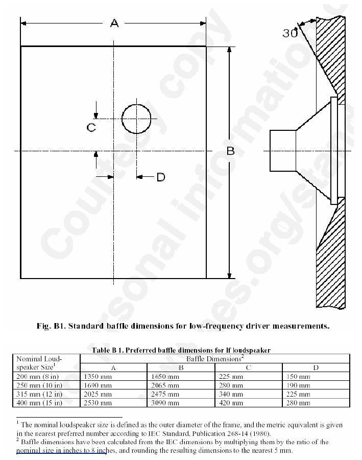
IEC Baffle:
- I'm using a Dell Mini 10v netbook along with the Dayton Omnimic Measurement Software/Mic, using the FFT impulse
- My goal is to measure both FR and Distortion of various drivers
- I'm going to build a scaled version of the IEC baffle. I think mine is approximately 70% the size of the smallest IEC baffle and follows the same dimensioning (albeit, scaled). Therefore, my baffle size would be ~ 945cm x 1155 cm (if I decide not to increase it). The reason I want to scale it is simply to get the dang thing upstairs! 😉
- My results are to be posted on a car audio forum, and I plan to test drivers under the size of 8 inches, though I am considering amending the bullet above and shooting for a baffle that allows up to 12" driver testing.
- I will be measuring in my upstairs room, which is completely bare sans carpet and walls, and is approximately 17x25' (I'll have to get final measurements as it's close to 500sqft).
- The baffle will have a square cut out of it to allow for swapping blanks more easily... pretty much like Zaph has done.
- I'm married, with 1 kid, and 2 golden retrievers. I like long walks on the... wait... wrong forum. 😉
Okay, hopefully that should get the basics out of the way.
I've got a technical background, so I'm not a dummy, but I swear, the notion of speaker measuring gets me wrapped up like a squirrel under a school bus. Maybe I'm just waaaaaay overthinking this, but I'd like your guys' help with this.
I get tripped up how one can properly measure a speaker, say, in the home. You can't surpass baffle diffraction, so how do you do anything about it? Is this the point at which you make both nearfield and farfield measurements (ie: ~1cm, and 1 meter away, respectively)?
If so, let's take this example to check my brain:
For instance, if you measure a 3" driver from 20-20k to see the FR and IMD, you put the mic right in front of the driver in order to pick up low end response but also remove artificats of baffle step, and farfield + gating to get higher frequency response, then 'stitch' the two FRs together at the "breaking point". At least, that's my understanding.
I've seen the number "10950" thrown around as the number to divide by your speaker's diameter (in cm) to get a "breaking point" between NF anf FF measurements where the two responses are stitched.
Where does 10950 come from? It isn't speed of sound in cm/s and it isn't quarter speed of sound... so, why do we use that?
Moving on...
For example, let's say I have the 3" (7.62cm) driver, then I go ...
10950cm/7.62cm = 1437hz.
So, I would stitch the NF and FF measurements together at approximately this frequency, as far as I understand.
Now, something that's more pertinent to me:
First, I don't beleive my software will allow for stitching. It does allow for shifting, though, I believe. This simply means that I wouldn't be able to cut off part of the response curves I don't want to get a single pretty FR.
Secondly, given my room size, do I really need to bother with gating and nearfield at all, or can I do away with farfield and just do nearfield only?
For some reason, I have the hardest time seeing why the two different methods (nearfield/farfield) are needed.
The results I'm shooting for here are relative; how does one driver behave compared to another? The data is intended to show this. I do not want my data to be taken out of context and viewed as absolute because there's just no way for me to feel 100% confident that my test methods and hardware are up to snuff with industry standards. Of course, when one says "relative", then anything is good enough as long as nothing changes, right? Well, it depends. For me, in this case, I'm shooting for having a well thought of test plan and am doing my homework to the extent plausible so if someone challenges my data, I can point to the rationale that drove me towad the test plan. Is that a fair methodology?
I do appreciate everyone looking at this. I know it's quite a lengthy read, but this is something I want to have a firm grasp of before I start posting plots as "gospel" (which they are often taken as, since people only look at pictures and not explanation of the test setup).
Thanks,
Erin
These are the sources I've been reading:
http://www.kirchner-elektronik.de/~kirchner/DIPOL-CARDIOIDeng.pdf
http://www.fesb.hr/~mateljan/arta/AppNotes/AP4_FreeField-Rev03eng.pdf
IEC Baffle:
Last edited:
Near field will go badly wrong at higher frequencies. Farfield will either require alot of space and a long pole or will go badly wrong at low frequencies.
Sorry can't help with you numerical question its not a guide I have ever heard of.
Hence the requirement for both.
There is another option as drivers tend to behave close to their simulation at low frequencies so you could simulate the low frequency response. But you will need to measure the high frequency response to see cone breakup.
IEC baffles do cause baffle diffraction you can use the FRD tools to work out what it is then try to remove it. But most people just put up with it.
FRD Consortium
Some help here:-
FRD Consortium tools guide
One of the FRD tools alows you to stitch so you can use that if you want to get a response that looks right.
Regards,
Andrew
One of the differences with different sized drivers is how they behave off axis (their dispersion).
You might be interested in how a driver measures on its intended baffle. Failing that (and you say you are doing auto measurements in your home), you might just want to exclude the baffle influence altogether. This would simply mean that you do your farfield measurements only down to the frequency where the test baffle is largely keeping the sound in front of it. ie, you are not excluding the baffle, only the change that can happen when the baffle dimensions 'run out'.
You may be able to ignore this in practice due to the size of your test baffle and the fact that indoor farfield measurements are usually limited to such a frequency anyhow. If you position your speaker at half the ceiling height to avoid the floor/ceiling reflections and gate the measurement within the time before those particular reflections, and you ensure a similar space behind/beside the driver and mic, you may not get far below a few hundred hertz. This has nothing to do with the driver size.
This may be OK as nearfield measurements are typically OK up to around/beyond this point. For off axis measurements I would want to be farfield for as low as the gating allows. This is necessary as the total sound reduces when the sound off axis drops off, even if it measures flat on axis. Once you put it into a real car, you'll want to be aware of this.
One more thing. There is such a measurement as dual gating. This is where the software uses the clean gated impulse to show the response above the frequency it is capable of, then uses the 'dirty' rest of the impulse to recreate the low end. This is not a bad estimate, at the very least it might give you a guide pplot for splicing your nearfield info.
- Status
- Not open for further replies.