How do I safely measure the output impedance of a valve amp? GM70 DHT in this case. The methods I have seen refer to SS amps, comparing infinite to known load, and that doesn't seem appropriate for a valve amp. I have sig gen, various voltmeters and a dual beam scope.
Would it work simply using two reasonable resistors (say 5 and 20 ohms) and calculating from there?
Would it work simply using two reasonable resistors (say 5 and 20 ohms) and calculating from there?
Last edited:
Would it work simply using two reasonable resistors (say 5 and 20 ohms) and calculating from there?
That's what I do. See attached Excel file for calculation (zip file password is "impedance").
Attachments
Yes that's how I do it. But I allow for some danger and go 100ohms for my high impedance reference measurement, just to give me more span to work with.
If your amp's OPT has very high turns ratio I would probably only go up to 50ohms.
(Speakers can have impedances way higher than the nominal, so I assume that should be safe).
Btw, if the amp is SE or 'pure class-A push-pull, you can go much higher while it is running. You don't want the OPT unloaded during turn on/off transients, but during operation these topologies are nut supposed to shut off during the cycle so you should not have a condition where one winding suddenly goes open circuit (as you will in a low bias class-AB at large excursions). So I think it is safe to go very large on the load resistor to get an even better 'almost open' reference measurement.
Somebody arrest me on this if I am wrong please...
Nice procedure. To be as close to reality one could do this testThat's what I do. See attached Excel file for calculation (zip file password is "impedance").
with 8 ohm and 10 ohm. But 8 and 12 is close.
Not with tetrode/pentode amp.Btw, if the amp is SE or 'pure class-A push-pull, you can go much higher while it is running.
Not with tetrode/pentode amp.
Aha! Because a tetrode and pentode have such high plate impedance? Should I concider these more akin to current sources in regards to output Z and therefore the primary winding looks almost unloaded?
Thanks for correction.
Basically yes.Because a tetrode and pentode have such high plate impedance?
Take the plate curves for some output triode and some output pentode, draw the horizontal load line and look at the full plate voltage swing in both cases 🙂Should I concider these more akin to current sources in regards to output Z and therefore the primary winding looks almost unloaded?
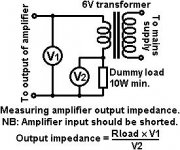
It's a method where you feed an external 6V signal into the output of the amplifier.And I don't understand that at all. 😕
It opens perfectly in a mac, the first is a zip file with zip-password, this unpacks@tikiroo: when attempting to open the Excel file I get a "file damaged" message. Any clue?
the file , which opens with neooffice ( a libre office distribution for mac's)
Sorry about that, it was just a basic calculation:
R1= test load 1 (e.g. 12 ohms)
R2= test load 2 (e.g. 8 ohms)
V1= voltage measured at the output with R1
V2= voltage measured at the output with R2
Output impedance = ((R1R2(V1-V2))/(R1V2-R2V1)
R1= test load 1 (e.g. 12 ohms)
R2= test load 2 (e.g. 8 ohms)
V1= voltage measured at the output with R1
V2= voltage measured at the output with R2
Output impedance = ((R1R2(V1-V2))/(R1V2-R2V1)
With tube amps, I load them with a resistor of appropriate value ( 8 ohms for the 8 ohm tap, for example). Running a tube amp without a load will have the output stage operating at a different point on its operating characteristic. You would get a faulty result using a measurement with this connection. So, I do the first measurement with 8 ohms at the 8 ohm tap. Drive the amp with a sine signal at maybe a watt or so, measure the voltage across the 8 ohms (save), then parallel the eight ohms with what will lower it to say, 4 ohms, and read the voltage. Save. Calculate the output impedance from these measurements.
Thanks. Is there any reason to not use 8 and 16 ohms? My amp only has an 8 ohm tap, without opening it up. It has parallel output binding posts, so that helps.
And is it worth testing at different frequencies too?
And is it worth testing at different frequencies too?
Last edited:
I seem to racall that I indeed get slightly different readings going from 100ohm to 50ohm than if going from 8ohm to 4ohm. I usually blame this on the resistance in the wiring starts to show when a low resistance is used giving a little more parasitic loss.With tube amps, I load them with a resistor of appropriate value ( 8 ohms for the 8 ohm tap, for example). Running a tube amp without a load will have the output stage operating at a different point on its operating characteristic. You would get a faulty result using a measurement with this connection. So, I do the first measurement with 8 ohms at the 8 ohm tap. Drive the amp with a sine signal at maybe a watt or so, measure the voltage across the 8 ohms (save), then parallel the eight ohms with what will lower it to say, 4 ohms, and read the voltage. Save. Calculate the output impedance from these measurements.
But perhaps it is as much the operating conditions of the tube's as well. Makes sence.
I will still test at the extremes since a real speaker can vary wildly in impedance and an amp must tolerate that anyways.
I also test at a few frequencies since the reading do differ a little.
Ps. I am very casual (not careful) with my own builds. I built it so I should be able to fix it.)
Using the 8 ohm output, and load with 8 ohm resistor, note voltage, thenThanks. Is there any reason to not use 8 and 16 ohms? My amp only has an 8 ohm tap, without opening it up. It has parallel output binding posts, so that helps.
And is it worth testing at different frequencies too?
use 16 ohm, note voltage and calculate.
8 or 16 ohm resistors ( or any other values in the interval 4 - 16 ohm would do,
best would be 6 and 10 ohm )
If the amp does not have any negative feedback, then the damping factor will vary according to frequency.
Take a non-feedback triode output stage (either single ended, or push pull).
Then . . .
At really low frequency, the inductance of the secondary increases the damping factor.
At really high frequency, the leakage reactance from the primary to the secondary reduces the damping factor.
If the amplifier is a non-fedback Beam Power or Pentode output (either single ended, or push pull),
Then the damping factor will be really low at mid frequencies, except at very low frequencies where the secondary inductive reactance provides some damping. And in some cases, if the primary distributed capacitance is high enough, that impedance will transform to a medium impedance at the secondary, which will give some damping factor at high frequencies.
If a UL amplifier is a non-feedback amp (other than the feed back of the Ultra Linear output stage), for either a single ended, or push pull output stage, the damping factor at low, mid, and high frequencies will fall somewhere between the Triode and Pentode/Beam Power damping factors as listed above.
Adding global negative feedback changes all the above damping factors.
See how that works?
Last edited:
- Home
- Amplifiers
- Tubes / Valves
- Measuring power amp output impedance