I usually measure output impedance of a completed amp fed from the mains supply via the installed PSU.
I usually get around 40milli-ohms to 80milli-ohms.
Today I am measuring a 3886 chipamp while it is being fed from a dual polarity Lab Supply.
Results, all at 1kHz sinewave, for 3 different supply voltages:
Supply Vccee . output into 8r0 . into open circuit
. . 20V . . . . . . 2804.1mVac . . . 2806.2mVac
. . 40V . . . . . . 2822.9mVac . . . 2824.4mVac
. . 63V . . . . . . 2822.9mVac . . . 2824.4mVac
Output impedance = [Vopen / Vinto8r * 8r] - 8r
for 20V, 6.0milli-ohms
for 40V & 63V, 4.3milli-ohms
Q1.) is the output impedance really that low?
Q2.) is the formula correct?
Q3.) why does the low supply voltage impedance increase by 1.7milli-ohms?
The test (~1W into 8r0) output voltage and the output current are well below the limits for the chipamp output stage.
Yet the 20V result shows the amp gain has dropped from 10.25times to 10.18times.
The supply voltage is 10Vdc and the output voltage is 3.96Vpk
This result contradicts what I was being told in other Threads a few weeks ago.
I asserted that amplifier gain falls as the supply rail voltage moves down towards the output voltage.
Comments welcome
Last edited:
Q1.) is the output impedance really that low?
Yes, and 6 mOhm is a bit high for an amp with lots of feedback (not very important, since the cable impedance will swamp it anyway).
Your way of doing it has the inconvenience of needing an extremely precise AC voltage measurement, which can be a problem.
It is much simpler to connect the amp output to GND and inject an AC current in the amplifier output, for example using another amp and a 8 ohm resistor. The voltage at the amp's output gives the impedance, an you can also visualize it on a scope, FFT it, whatever, to reveal all sorts of gremlins (crossover distortion has nowhere to hide). You can also inject, for example, a 50 Hz 1 amp current and a 1kHz 10mA current, with 2 extra amps. Then you can measure the intermodulation at the amplifier output. Etc.
It would seem from many sources that the expression is fine and about the only basis for practical low impedance measurement.......Output impedance = [Vopen / Vinto8r * 8r] - 8r.....
Q1.) is the output impedance really that low?
Q2.) is the formula correct?
Q3.) why does the low supply voltage impedance increase by 1.7milli-ohms?.....
The method may vary among test authorities but this detail from a review tester at least clarifies how it may be done commercially.
The relevant section is the editorial in the conclusion.
Basic Amplifier Measurement Techniques | Audioholics
Andrew, the small perturbations on the supply voltage should not change voltager gain, except when you get to clipping.
Remember that Zout is really a differential value. The correct way to measure it is as follows:
- measure Vout with a specific load, say 8 ohms, and calculate Iout.
Example: 8V out, at 8 ohms is 1 amp;
- change load to say 4 ohms, measure Vout again, and calculate Iout.
Example: now Vout drops to 7V, which gives Iout = 7 / 4 = 1.75 amps.
Now calculate Zout = change in Vout (8-7) / (change in Iout (1 - 1.75) = 1.3333 ohms.
Jan
When I need to measure an amp output impedance, I first set the output voltage with a load, both having simple numbers.
For example, 8 Vrms on a 8 Ohm power resistor makes the amplifier delivering a current of 1 A.
Then I remove the load. The output voltage changes, usually only slightly.
The voltage difference is equal to the value of the output impedance.
No calculation.
For example, 8 Vrms on a 8 Ohm power resistor makes the amplifier delivering a current of 1 A.
Then I remove the load. The output voltage changes, usually only slightly.
The voltage difference is equal to the value of the output impedance.
No calculation.
Peufeu's method is the only valid way to measure the impedance, for a number of reasons.
One the most important is that for amplifiers with feedback, the output impedance is not real: it is complex, almost purely inductive.
When the small inductive drop is subtracted from the huge quadrature output voltage, it is completely overwhelmed, leading to enormous errors.
The differential load method is a remnant of the tube era, when the output impedance of an amplifier was of the same order as the load, or even much larger in some cases, but it is totally unapplicable to modern semiconductor amplifiers.
It is much simpler to connect the amp output to GND...
I'm having difficulty visualising this... If the above was INPUT, I get it, but I'm not sure...
Brian
He means the input (= no signal)I'm having difficulty visualising this... If the above was INPUT, I get it, but I'm not sure...
Brian
Mr. Pass has an article entitled "Mosfet Citation 12" at www.firstwatt.com. He described at the end of it the method as posted earlier by peufeu.Thanks for that - it makes sense now.
Brian
When I need to measure an amp output impedance, I first set the output voltage with a load, both having simple numbers.
For example, 8 Vrms on a 8 Ohm power resistor makes the amplifier delivering a current of 1 A.
Then I remove the load. The output voltage changes, usually only slightly.
The voltage difference is equal to the value of the output impedance.
No calculation.
Forr, the potential issue here is that with zero Iout you are in the amp xover region and the Zout may be different there from the normal operating regime.
That's why I suggested to use two different load and do the (very simple) algebra.
Peufeu's method is better but a bit more involved that a simple multimeter.
Jan
Using a resistor ratio to measure impedance is a good method if all the impedances are more or less in the same ballpark (for example, a wheatstone bridge), however in the case of an amplifier this is not the case, as the expected output impedance is 1000x lower than the expected load impedance.
Also the output impedance is nonlinear and we would like it to minimize this nonlinearity, which needs some measurements that reveal it...
The standard way to measure an impedance is to send a current through it and check the voltage. If the current is AC, then measurement DC offsets are eliminated. If the current is a pure sine wave (or a sum of sines) the usual stuff can be done, FFT, harmonics, etc.
Measuring the distortion of an amplifier is difficult, since the distortion is hidden in the large output signal. The interesting part is distortion, but it is maybe 0.01% of the whole signal.
However when the amp's input is grounded and a current is injected in the output, a perfect amp would have an output voltage of zero, so the whole voltage that is measured at the output is 100% interesting.
I tested two methods :
1- make the amp output a low AC voltage in a very low resistance (like 0.1-0.5 ohm)
This is more or less the method suggested in this topic. It does not give a precise impedance value, but as the AC frequency is swept it will give impedance variations versus frequency. More important, it shows crossover distortion much better than a 8 ohm load, since it depends on current, not voltage.
2- inject current with another amp
This is a much better way to precisely measure output impedance since the injected current is known, the voltage is known... the driving amp should be low-distortion of course... this is the best method since it gives current and voltage, which can be plotted in XY mode, etc.
There was an interesting conversation with Pavel (PMA) in this thread, check it out :
http://www.diyaudio.com/forums/ever...iers-have-their-own-sound-12.html#post3835879
Last edited:
One thought came immediately to mind on this. If the return current and feedback nodes are less than ideally placed (and I know you will have gone to great trouble getting this right) then any results are skewed. Its easy to get the amplifier output voltage to decrease or increase as a load is connected by moving for example moving a speaker return current just a millimetre or two either way from a theoretically correct position. When you are talking measured values of only 6milli ohms or so, well can you be sure all the layout and wiring is correct to give validity to such low measured values.
Hi Jan, i have test this way today.Andrew, the small perturbations on the supply voltage should not change voltager gain, except when you get to clipping.
Remember that Zout is really a differential value. The correct way to measure it is as follows:
- measure Vout with a specific load, say 8 ohms, and calculate Iout.
Example: 8V out, at 8 ohms is 1 amp;
- change load to say 4 ohms, measure Vout again, and calculate Iout.
Example: now Vout drops to 7V, which gives Iout = 7 / 4 = 1.75 amps.
Now calculate Zout = change in Vout (8-7) / (change in Iout (1 - 1.75) = 1.3333 ohms.
Jan
Here the results.(tested ampl.Ostirpper slew master. TEST FREC 1KHz)
8R/8,032V RMS 1,004A
4R/8,006V RMS 2,0015A
8,O32-8,006/1,004-2,0015=0,026R=26mR
Is it right?
Last edited:
Forr, the potential issue here is that with zero Iout you are in the amp xover region and the Zout may be different there from the normal operating regime.
That's why I suggested to use two different load and do the (very simple) algebra.
Peufeu's method is better but a bit more involved that a simple multimeter.
Jan
The method I use is only for a quick check of the output impedance at a fixed frequency. The value is most of the time very low as most usual amps are voltage sources, it should not change with the regime.
I sometimes used Pass-Peufeu's method but did not find it worth for simple tests.
Of course, scrutinizing the behaviour of output impedances with their method is very interesting for the science of amplification, however, I've not seen great changes in amp design inspired by the obtained results.
Last edited:
Hi Jan, i have test this way today.
Here the results.(tested ampl.Ostirpper slew master. TEST FREC 1KHz)
8R/8,032V RMS 1,004A
4R/8,006V RMS 2,0015A
8,O32-8,006/1,004-2,0015=0,026R=26mR
Is it right?
Yes looks OK, 26.1mR when rounded 😉. You probably recognized the negative sign on the current difference and corrected for it correctly 😉
Jan
I have not abandoned you.
I am reading all your comment, sometimes two or three times to make sure I pick up all the details.
I didn't expect so much from three simple questions!
I am reading all your comment, sometimes two or three times to make sure I pick up all the details.
I didn't expect so much from three simple questions!
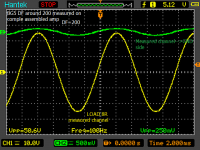
I do not know if it is correct but I am doing it this way:
- 2 amplifiers (or two channels)
-channel A--> grounded input
-channel B--> generator at the input
-resistive load connected between A and B
So If we have current and voltage than we can get the impedance values at some frequences and make some impedance curve out of it.
- 2 amplifiers (or two channels)
-channel A--> grounded input
-channel B--> generator at the input
-resistive load connected between A and B
So If we have current and voltage than we can get the impedance values at some frequences and make some impedance curve out of it.
Attachments
Hi i believe that is more useful if you can post a diagram for this test configuration.🙂Using a resistor ratio to measure impedance is a good method if all the impedances are more or less in the same ballpark (for example, a wheatstone bridge), however in the case of an amplifier this is not the case, as the expected output impedance is 1000x lower than the expected load impedance.
Also the output impedance is nonlinear and we would like it to minimize this nonlinearity, which needs some measurements that reveal it...
The standard way to measure an impedance is to send a current through it and check the voltage. If the current is AC, then measurement DC offsets are eliminated. If the current is a pure sine wave (or a sum of sines) the usual stuff can be done, FFT, harmonics, etc.
Measuring the distortion of an amplifier is difficult, since the distortion is hidden in the large output signal. The interesting part is distortion, but it is maybe 0.01% of the whole signal.
However when the amp's input is grounded and a current is injected in the output, a perfect amp would have an output voltage of zero, so the whole voltage that is measured at the output is 100% interesting.
I tested two methods :
1- make the amp output a low AC voltage in a very low resistance (like 0.1-0.5 ohm)
This is more or less the method suggested in this topic. It does not give a precise impedance value, but as the AC frequency is swept it will give impedance variations versus frequency. More important, it shows crossover distortion much better than a 8 ohm load, since it depends on current, not voltage.
2- inject current with another amp
This is a much better way to precisely measure output impedance since the injected current is known, the voltage is known... the driving amp should be low-distortion of course... this is the best method since it gives current and voltage, which can be plotted in XY mode, etc.
There was an interesting conversation with Pavel (PMA) in this thread, check it out :
http://www.diyaudio.com/forums/ever...iers-have-their-own-sound-12.html#post3835879
- Status
- Not open for further replies.
- Home
- Amplifiers
- Solid State
- Measuring Power Amp Output Impedance