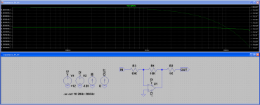
In the schematic below, my understanding is that R3 sets the input impedance and R2 sets the output impedance.
I'm using the method mentioned in this forum and in others of injecting a 1 Unit Current source into the node to be measured, then displaying the Y axis as Linear and then displaying the trace as V/I.
For 'IN' I get a 10K input impedance as expected but for 'OUT' I also get 10K - where I would expect 1K.
Can anyone explain what's going on here? I'm using this basic model to check my methods before checking impedances on a more complex simulation.
Thanks.
Attachments
Check your -12 V source. I can not see your AC stimulus in your circuit - but the AC stimulus should be at the output.
The idea is: you apply a current at the output and then you measure the circuit respose: Rout = Vout/Iout
To measure output impedance correctly use the attached circuit.
Use AC anaylysis for output impedance.. you get the impedance over frequency with AC anaylysis.
Greetings
Udo
The idea is: you apply a current at the output and then you measure the circuit respose: Rout = Vout/Iout
To measure output impedance correctly use the attached circuit.
Use AC anaylysis for output impedance.. you get the impedance over frequency with AC anaylysis.
Greetings
Udo
Attachments
Last edited:
- Status
- Not open for further replies.