Thank you so much,Divide permeability by the free-space value of 4*pi x 10^-7 as you correctly wrote in #3. For typical electrical steel, it should be around 3000 if I remember correctly.
I meant how to derive permeability from any point on B-H cure, ie. should I use tangent on the curve at operating point, or to use line crsooing from zero to operating point and then calculate dB/dH at that point?
Thanks again,Since the final goal is to set the lower cutoff frequency, determined by the source resistance Rpp and the primary inductance L, perhaps it makes sense to design for a given inductance. Then calculate the optimal geometry for the peak current. The optimal geometry parameters are the core cross-section A and the average magnetic path length l (lower case L). From these parameters you can select a suitable laminate material. Then use a 100 turn test winding, measure the inductance with medium current (voltage) and you will get L. From these you can calculate n number of (primary) turns.
Of course, if you know the relative permeability, you can reverse the design order.
I needed to have some information about this material to be able to base the design on it. I needed to know material Permeability to estimate air gap size, and of course I should adjust the actual air gap size in the amp.
I'm in the process of creating an Excell file to design OPT and Power transformer and mabe PSU filtering choke for tube amps, and I will post it after it is finished.
Regards
Sajad
I have a small M42 transformer with mumetal lamination. The core area is 1.8 x 10⁻⁴ m2, magnetic path length is 0.1 m. I measured the inductance with 400 turns, it is 10.13 H. From these data I calculated the ur relative permeability = 28500. Or Al = L/n2 = 64375 [nH]. But this is a special iron, it can not handle high flux. I will use it for low signal level, no power.
Yeah those mumetal stuff are perfect for loew level audio transformers such as input or inter stage transformers but can't withstand high flux in an OPT.
Yes. Permeability is the slope, and varies everywhere on the curve. Note that this is a "static" curve, made as if hysteresis were zero, and could be imagined as being drawn with varying DC conditions with a very small AC component whose slope is measured.I meant how to derive permeability from any point on B-H cure, ie. should I use tangent on the curve at operating point,
All good fortune,
Chris
Have you to tried to plot a saturation curve for your 'unknown' laminations and compare it with a saturation curve for 'known' laminations ? it won't give you permeability figures but will give you a comparison against a core made from iron that is known to be ordinary power transformer iron - if your unknown core has the same saturation curve as the ordinary iron then it is a fair bet that the unknown core is also ordinary iron.
Assemble your 'known' core and wind around 100-150 turns - scrap wire that has been pulled from a junked transformer is ok for this, make it at least 0.5mm thick - setup the circuit in the pic - start at 0V and increase the voltage across the test transformer in 1V steps - at each step note the voltage across the test transformer and the corresponding voltage across the 10 ohm resistor - by measuring the voltage across the resistor, you are measuring the current through it - the voltage across the 10 ohm resistor will remain reasonably low and constant until you start to reach core saturation where it will start to rise - at this point you may want to reduce the step voltage increase to 0.5V or less - once the core is fully saturated the voltage across the 10 ohm resistor will increase in proportion to the voltage across the test transformer - the 10 ohm resistor can get quite hot - only leave power connected long enough to note the voltage readings - DO NOT omit the isolating transformer.
Use the recorded voltages to plot a saturation curve. Do the same again using your 'unknown' core - compare the two plotted curves - while it helps greatly for comparison purposes if the x-section of each core is the same they don't have to be as the it is the magnetic material that determines the shape of the curve - a smaller core will require less volts to reach saturation and you may need to adjust the size of the step voltage and or the resistor and number of turns. A core as used in a domestic radio would be considered ordinary iron and the 'knee' point where it starts to saturate will be more pronounced - sharper than a grain oriented silicon which usually has a more gentle curve.

Yes, slope is indeed dB/dH, but in actual practice, it is easier to do (B2-B1) / (H2-H1). Also, the permeability around the origin is always linear. One could then compare that starting value with that around Bmax of his/her choice. Bsat is easy to obtain by visual inspection.I meant how to derive permeability from any point on B-H cure, ie. should I use tangent on the curve at operating point, or to use line crsooing from zero to operating point and then calculate dB/dH at that point?
For transformers, Bmax is usually 70% of Bsat, as we need to account for line variations etc.
Now I get it! So I should use a different DC current and plot the 'Normal Magnetizing Curve' to calculate permeability at any point.Yes. Permeability is the slope, and varies everywhere on the curve. Note that this is a "static" curve, made as if hysteresis were zero, and could be imagined as being drawn with varying DC conditions with a very small AC component whose slope is measured.
All good fortune,
Chris
I guess using AC signal and ploting hystersis curve will only get me to 'Average permeability', am I correct?
Thank yo so much, you gave me everything needed for my tests, now I can get some info on this material.Have you to tried to plot a saturation curve for your 'unknown' laminations and compare it with a saturation curve for 'known' laminations ? it won't give you permeability figures but will give you a comparison against a core made from iron that is known to be ordinary power transformer iron - if your unknown core has the same saturation curve as the ordinary iron then it is a fair bet that the unknown core is also ordinary iron.
Assemble your 'known' core and wind around 100-150 turns - scrap wire that has been pulled from a junked transformer is ok for this, make it at least 0.5mm thick - setup the circuit in the pic - start at 0V and increase the voltage across the test transformer in 1V steps - at each step note the voltage across the test transformer and the corresponding voltage across the 10 ohm resistor - by measuring the voltage across the resistor, you are measuring the current through it - the voltage across the 10 ohm resistor will remain reasonably low and constant until you start to reach core saturation where it will start to rise - at this point you may want to reduce the step voltage increase to 0.5V or less - once the core is fully saturated the voltage across the 10 ohm resistor will increase in proportion to the voltage across the test transformer - the 10 ohm resistor can get quite hot - only leave power connected long enough to note the voltage readings - DO NOT omit the isolating transformer.
Use the recorded voltages to plot a saturation curve. Do the same again using your 'unknown' core - compare the two plotted curves - while it helps greatly for comparison purposes if the x-section of each core is the same they don't have to be as the it is the magnetic material that determines the shape of the curve - a smaller core will require less volts to reach saturation and you may need to adjust the size of the step voltage and or the resistor and number of turns. A core as used in a domestic radio would be considered ordinary iron and the 'knee' point where it starts to saturate will be more pronounced - sharper than a grain oriented silicon which usually has a more gentle curve.
View attachment 1292353
Dear friend, you wrote a lot of output transformers... you made them for guitar amplifiers... is it possible to publish a picture of these creations? Did you make the guitar amplifier yourself?Hi everyone, first time poster long time reader!
For a long time I've wound many output transformers for guitar amps and due to Low-Fi nature of guitar amps OPTs turnrd out to be good enough, but this time I'm in process of winding my first Hi-Fi tube amp output transformer, and after gathering information from several sources like RDH4, Wolpert's books and mostly important Patrick Turner's website, I realized that I need to find a good GOSS material for this purpose;
After alot of searching for available core materials I could only find some Non-grain oriented silicon steel (NOSS) material from china that nearly there is no data on this material anywhere! The seller only knows that it is M470 NOSS material and he's not even sure about it!!
With this material I know my OPTs will weight like a battleship but I don't have any other option right now.
So I'm wondering if there is any method that I can use to measure permeability vs flux density of an unknown core lamination using maybe an oscilloscope and a test winding with known turns??
Any help would be greatly appreciated!
Sajad
Using a non oriented steel might not be a problem at all for a guitar amp. The OPT needs to be good enough to cope with max power at lowest guitar frequency which is 83 Hz. If use 1500 for relative permeability, I suspect you won't be far off.
Attachments
Last edited:
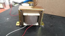
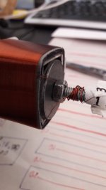
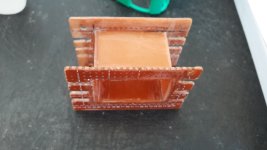
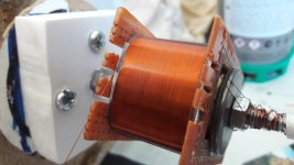
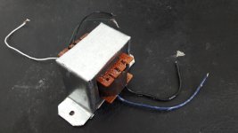
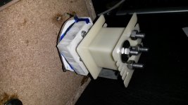
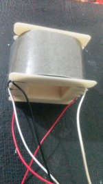
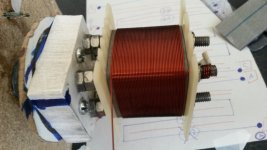
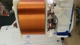
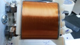
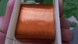
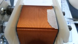
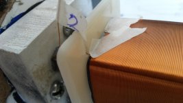
Of course my friend, Fortunately I still have a few pictures from my old work which I will attach them here;
These transformers are from my early work which I used my old handmade manual lathe to wind. Lately I've built a CNC automated winding machine which made my work much much easier.
BTW in the field of audio art is as important as the knowledge; I assume you already know that! right?😉
These transformers are from my early work which I used my old handmade manual lathe to wind. Lately I've built a CNC automated winding machine which made my work much much easier.
BTW in the field of audio art is as important as the knowledge; I assume you already know that! right?😉
Attachments
-
 20160913_142644.jpg291.3 KB · Views: 67
 -
 20161124_111742.jpg208.5 KB · Views: 79
 -
 20161128_121027.jpg417.8 KB · Views: 83
 -
 20161130_135933.jpg509.9 KB · Views: 79
 -
 20161202_162254.jpg467.6 KB · Views: 75
 -
 20160826_230544.jpg281 KB · Views: 76
 -
 20160913_142644.jpg291.3 KB · Views: 75
 -
 20160912_214854.jpg338.9 KB · Views: 74
 -
 20160912_111303.jpg229.3 KB · Views: 65
 -
 20160912_164746.jpg264.2 KB · Views: 68
 -
 20160912_120957.jpg305.9 KB · Views: 66
 -
 20160912_101603.jpg270.3 KB · Views: 71
 -
 20160911_094906.jpg287.9 KB · Views: 107
 -
 20160912_094217.jpg274.9 KB · Views: 64
 -
 20160912_101603.jpg270.3 KB · Views: 73
Last edited:
I'm lucky that GOSS is available here. I would guess it's available in most of the developed world it's just knowing where to find it as it's sold to industry not for DIY, so isn't marketed to us. Maybe try enquiring locally; find out where the iron came from for you local mains electricity substation, that might point you in the direction of a supplier.
Best of luck
Best of luck
While it is nice to be able to use grain oriented EI laminations for output transformers, I believe perfectly acceptable transformers can be wound using ordinary power transformer iron, this is certainly the case with guitar amp transformers which typically have a response from around 75Hz to around 15KHz. I've rewound output transformers from Fender, Laney, Selmer and Marshall and they all used 0.5mm thick laminations which to me points to ordinary non grain oriented power transformer iron, the winding layout I recall was nothing special and more or less the same for all of them I've attached the winding layout for the AOR Laney 50W this type of winding layout seems to be quite common for guitar amps.
I scratch built a Vox AC15 copy for my son some years back, the output transformer was wound from a scrapped solid state PA amp power supply transformer, it just happened to be the right size, I copied the Laney AOR winding layout.
I managed to talk my son into a playing a 3min demo of the amp on the day he picked it up -
Hi
This is the way to determine relative permeability of core laminations
I used many times with god results in praxis.
This is the only accurate way, i tried others but without good results.
.

This is the way to determine relative permeability of core laminations
I used many times with god results in praxis.
This is the only accurate way, i tried others but without good results.
.
- Home
- Amplifiers
- Tubes / Valves
- Measuring magnetic permeability of an unknown transformer core material