Here is another, more practical, example with real-life measurement on actual hardware.
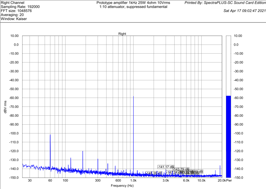
The measurements below were done on a prototype amplifier with about 100dB of loop gain at 20kHz and 140dB at 1kHz. The amplifier was delivering 25W into a 4ohm resistor - that is, the output level is 10Vrms in each case, verified by an RMS voltmeter. The signal is fed into the sound card (the same E-MU 0204 as above) via a 1:10 (-20dB) divider, and the fundamental/test signal is additionally suppressed by about 60dB to minimize the sound card's own distortion.
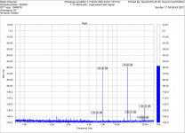
As expected, the 1kHz THD test is not particularly revealing:
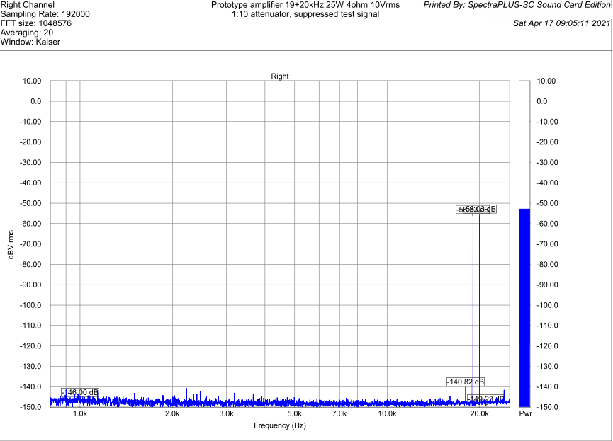
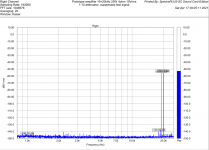
The standard 19+20kHz IMD test is not much better:
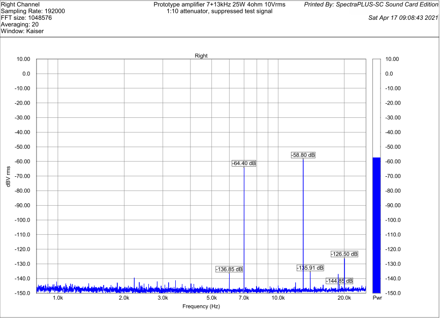
The 7+13kHz test actually shows some measurable intermodulation products:
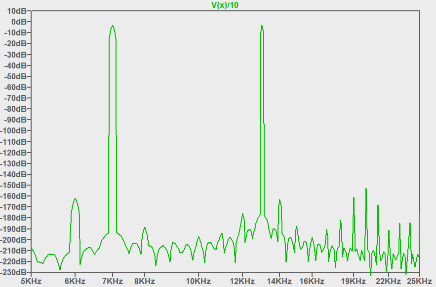
The relative levels of various intermodulation products are in a reasonable agreement with the simulation:
The measurements below were done on a prototype amplifier with about 100dB of loop gain at 20kHz and 140dB at 1kHz. The amplifier was delivering 25W into a 4ohm resistor - that is, the output level is 10Vrms in each case, verified by an RMS voltmeter. The signal is fed into the sound card (the same E-MU 0204 as above) via a 1:10 (-20dB) divider, and the fundamental/test signal is additionally suppressed by about 60dB to minimize the sound card's own distortion.
As expected, the 1kHz THD test is not particularly revealing:
The standard 19+20kHz IMD test is not much better:
The 7+13kHz test actually shows some measurable intermodulation products:
The relative levels of various intermodulation products are in a reasonable agreement with the simulation:
Attachments


Last edited: