Is there anything wrong with the R+L measurement?
Monitor the voltages across the R & the L until you find the Frequency where the voltages match. At the matching voltage, the phase shift is 45° and the Frequency is the F-3dB.
Then use XL= 2PiLFwhich rearranged gives L= XL/2PiF (L in Henries for ohms and Hz)
Monitor the voltages across the R & the L until you find the Frequency where the voltages match. At the matching voltage, the phase shift is 45° and the Frequency is the F-3dB.
Then use XL= 2PiLFwhich rearranged gives L= XL/2PiF (L in Henries for ohms and Hz)
Is there anything wrong with the R+L measurement?)
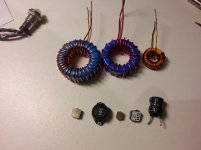
No Andrew there is nothing wrong, but like i said that's only one parameter i would like to set saturation currents cause most of the time times i don't have the core data and this is a nice setup to do a test fixture for those phantom core with strange colors and sizes...
In the R+L case just swap the resistor value to allow a range of frequencies to be measured.
The accuracy depends on the frequency meter, the resistor tolerance, and the quality of the voltage match. This gives a very tight tolerance for the inductor value at that particular frequency.
The accuracy depends on the frequency meter, the resistor tolerance, and the quality of the voltage match. This gives a very tight tolerance for the inductor value at that particular frequency.
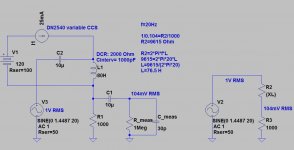
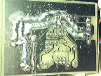
The formulae (in blue in the middle) seem to relate to the schematic on the right.
As far as I know this is wrong.
It works for a resistor for R2 but it does not work for an inductor for R2. The proportionality of voltages does not hold when the reactance is 90degrees phase shifted.
As far as I know this is wrong.
It works for a resistor for R2 but it does not work for an inductor for R2. The proportionality of voltages does not hold when the reactance is 90degrees phase shifted.
Missing files...
These are the files that got missing from post #1 in page #1
These are the files that got missing from post #1 in page #1
Attachments
-
 TESTPWM0.gif16.5 KB · Views: 552
 -
TEST_PWM_EPS.ZIP2.8 KB · Views: 137
-
 TESTPWM8.jpg56.5 KB · Views: 495
 -
 TESTPWM7.jpg65.3 KB · Views: 456
 -
 TESTPWM6.jpg65.3 KB · Views: 465
 -
 TESTPWM5.jpg59.2 KB · Views: 472
 -
 TESTPWM4.jpg68.3 KB · Views: 509
 -
 TESTPWM3.gif29.8 KB · Views: 530
 -
 TESTPWM2.gif29.6 KB · Views: 155

And these are the files missing in post #7 in page #1
Thank Youuuuuuuu! 🙂
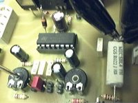
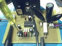
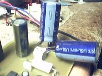
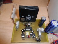
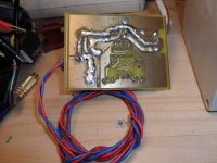
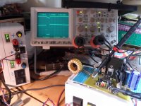
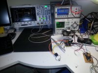
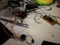
This post shows current state of the tool/prototype.
Four improvements were made:
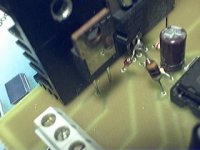
- Turn off speed up diode (1A schottky or 200V ultrafast) was added in parallel with 22r gate resistor.
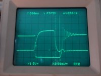
- Two small ferrite beads were added in series with FET gate (total .5~1uH) to achieve semi-resonant turn off, skipping partially or completely "miller" period. This gets faster edges when using the circuit as "square wave dummy load" for finding resonances in supply rails.
- A 470r potentiometer was added in series with the 100r resistor that is used to add a pole (LPF) to cancel the zero introduced by .022r current sense resistor inductance (~30nH, ~1nH/mm of pad spacing). This forms a variable divider. The oscilloscope probe is connected to the divider (100r to pot junction) and the pot should be adjusted for coherence of edges of current sense waveform.
- In the capacitor of this LPF (4.7n) ground connection was moved from PCB to sense resistor directly for more accurate waveform and to make grounding 2 oscilloscope probes to the same location easier (alligator clip directly to capacitor).
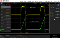
In the pictures showing oscilloscope CH1 is 1:1 probe and CH2 is 100:1 probe.
Four improvements were made:
- Turn off speed up diode (1A schottky or 200V ultrafast) was added in parallel with 22r gate resistor.
- Two small ferrite beads were added in series with FET gate (total .5~1uH) to achieve semi-resonant turn off, skipping partially or completely "miller" period. This gets faster edges when using the circuit as "square wave dummy load" for finding resonances in supply rails.
- A 470r potentiometer was added in series with the 100r resistor that is used to add a pole (LPF) to cancel the zero introduced by .022r current sense resistor inductance (~30nH, ~1nH/mm of pad spacing). This forms a variable divider. The oscilloscope probe is connected to the divider (100r to pot junction) and the pot should be adjusted for coherence of edges of current sense waveform.
- In the capacitor of this LPF (4.7n) ground connection was moved from PCB to sense resistor directly for more accurate waveform and to make grounding 2 oscilloscope probes to the same location easier (alligator clip directly to capacitor).
In the pictures showing oscilloscope CH1 is 1:1 probe and CH2 is 100:1 probe.
Attachments
These are the files that got missing from post #1 in page #1
I used your jig and created a concept version using a TL494 and it worked, I did this a few weeks ago.
Attachments

- Status
- Not open for further replies.
- Home
- Amplifiers
- Power Supplies
- Measuring inductors