I have been landed with the task of measuring a number of coils for consistency.
My first attempt was using an LCR meter to measure both Z, and Q. The DCR is already known. However, using an LCR meter the R value calculated is a couple of orders of magnitude greater than the true DCR.
IS this a failing of LCR meters?
So my next thought is to instead run a frequency sweep, with a known C in parallel with the coil to find the resonant frequency. Then calculate L and Q from the measured Z and R.
Any expert advice on whether i need to, or whether I'm being picky?
The R value displayed by the instrument is an equivalent value, incorporating all the losses at the measurement frequency: it has no way to guess what part is due to the ohmic resistance or the eddy currents, or the hysteresis, or the magnetic viscosity, etc etc, it simply measures the magnitude and argument of the impedance and presents the result according to your choice.I have been landed with the task of measuring a number of coils for consistency.
My first attempt was using an LCR meter to measure both Z, and Q. The DCR is already known. However, using an LCR meter the R value calculated is a couple of orders of magnitude greater than the true DCR.
This means that the equivalent resistance will always be larger (sometimes much larger) than the DCR, unless something is really wrong
Thanks, i suspected as much, without having ALL the knowledge to explain.
I.am looking to measure 'component Q' as a measure of winding uniformity, inter winding gap uniformity and the like. To be totally honest i am not convinced that Q is the best way, but i am attempting it anyway.
Just for interest, the DCR is in the milliOhm range, and the loss R calculated by the LCR meter is 30 Ohms.....
Using a known C i hope to establish a measurement criteria for coils, based on the parallel circuit Q. An accurate L measure would also be useful. I believe that performing a frequency sweep with this setup should give me an accurate result, and an arbitrary Q which i could use in further calculations, or as a subjective measure of consistency.
Does this sound feasible?
Thanks, i suspected as much, without having ALL the knowledge to explain.
I.am looking to measure 'component Q' as a measure of winding uniformity, inter winding gap uniformity and the like. To be totally honest i am not convinced that Q is the best way, but i am attempting it anyway.
Just for interest, the DCR is in the milliOhm range, and the loss R calculated by the LCR meter is 30 Ohms.....
Using a known C i hope to establish a measurement criteria for coils, based on the parallel circuit Q. An accurate L measure would also be useful. I believe that performing a frequency sweep with this setup should give me an accurate result, and an system Q which i could use in further calculations, or as a subjective measure of consistency.
Does this sound feasible?
Obviously not, or it should be a wideli known and well documented fact (and somehow compensated in the measuring technique, I assume it's poor measurement technique.My first attempt was using an LCR meter to measure both Z, and Q. The DCR is already known. However, using an LCR meter the R value calculated is a couple of orders of magnitude greater than the true DCR.
IS this a failing of LCR meters?
Considering all other parameters, equivalent resistance will be higher than simple DCR ... but not 1000:1 !!!
What Inductance and Resistance values are we talking about?
If very small values, probe/wiring/terminal/contact resistance may be higher than DCR of the part itself, same as when cheap multimeters show 0.5 to 1 ohms with probes shorted ... but definitely not 30 ohms.
FWIW I have an old and trusty Leader LCR 740 bridge,
An externally hosted image should be here but it was not working when we last tested it.
and it has 1 milli ohm resolution, go figure.
I modded it adding a precision Op Amp and a Led to better detect the Zero/null but that does not change the measurement precision, just makes it easier to see.
Recheck what you are doing, or maybe your meter is bad, not all meters.
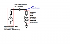
One way to measure inductor Q is to use a resonant-circuit technique. The inductor is connected to a very high quality film capacitor, and this LC circuit is stimulated by a low-Z pulse generator. The circuit resonates, and the ringing slowly dies away due to the damping provided by the (unwanted!) effective series resistance in the inductor. Then we use the logarithmic decrement method to extract the damping coefficient Zeta. Finally, Q = 1/(2xZeta) and we're all done. Of course this measures Q at the resonant frequency of the LC tank; you can measure Q at different frequencies by selecting different capacitors.
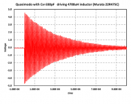
The first figure shows a conceptual schematic, and the second figure shows a captured scope trace from an actual L and C and pulse generator.
To apply the logarithmic decrement method, we observe that sinusoidal crest #6 is 4 volts, and crest #19 is 3 volts. Thus N=(19-6)=13, V1=4, V2=3. Applying the formula, delta = 0.2213 and the damping factor Zeta = 3.52E-3. Since Q = (1/2xZeta), Q = 142 for this inductor, at this frequency.
All of this is discussed in the "Quasimodo" thread here on this website. Find the thread, download the .pdf attached to post#1, look for Figure 12 with the red wiggles (I copied it here!), and read Appendix B.
Attachments
All,
Yes. I am familiar with resonant circuits (well familiar to degree level, if that means anything 🙂)
I have used 2 LCR bridges. Old Phillips meter, very good. Agilent hand held meter.
Both agree. Were talking 0.032 Ohms DCR, using a 10 Amp bridge; a L of 24.8mH , and Z of 158 Ohms @1kHz; Q of 4.8.
The series Rloss is 32 Ohms.
I am hoping to use the Q and L against design values to assess interwinding uniformity, or coil tightness (or relative slackness) and detect insulation losses out of spec, by virtue of an increase in Rloss and Q.
I really should run some numbers, I'm digging out Chris Bowicks "RF Circuit Design" as i speak (type)
My limited understanding is that Q is rather less meaningful for inductors, relating to resistive loss, rather than any resonant behaviour, since there should be a relatively small amount of parasitic interwinding capacitance.
My initial idea is to create a tank circuit with a known C, chosen to give a defined Q, when combined with and inductor of the Designed inductance. Deviation from this Q would indicate increased loss, or other variations from the designed coil. Tolerances can then be applied. All using a frequency sweep to find the Q peak, in a similar way as i have taken loudspeaker impedance curves ( I'm normally over that forum 🙂 )
The step response and decay approach is interesting too. Its probably a whole lot quicker. Perhaps also easier to apply using microcontrollers, or some other IC approach.
Last edited:
This seems to mean that the parallel losses are overwhelming, which is not necessarily exceptional at these frequencies.All,
Yes. I am familiar with resonant circuits (well familiar to degree level, if that means anything 🙂)
I have used 2 LCR bridges. Old Phillips meter, very good. Agilent hand held meter.
Both agree. Were talking 0.032 Ohms DCR, using a 10 Amp bridge; a L of 24.8mH , and Z of 158 Ohms @1kHz; Q of 4.8.
The series Rloss is 32 Ohms..
If your two instruments agree, taking into account the fact that Agilent (formerly HP and presently Keysight) and Philips (now ...?) are good, reliable makers, this probably means the result is OK.
Uniformity will have an effect on Q, but very minuscule unless the work has really been bungled.I am hoping to use the Q and L against design values to assess interwinding uniformity, or coil tightness (or relative slackness) and detect insulation losses out of spec, by virtue of an increase in Rloss and Q.
Insulation problems are not going to be detectable in this way, unlesss it is a straightforward short.
Your best guess would be to use an optimally wound coil as a reference for capacitance, and reject anything that is , say 30% higher. The losses would be minimally impacted by such problems.
You are probably going to make your own life very complicated: if you rely on manufacturers like Agilent and Philips and you have good cross-correlation between them, that is clearly the way to follow, unless you are very clever, or have very specific requirements.I really should run some numbers, I'm digging out Chris Bowicks "RF Circuit Design" as i speak (type)
My limited understanding is that Q is rather less meaningful for inductors, relating to resistive loss, rather than any resonant behaviour, since there should be a relatively small amount of parasitic interwinding capacitance.
My initial idea is to create a tank circuit with a known C, chosen to give a defined Q, when combined with and inductor of the Designed inductance. Deviation from this Q would indicate increased loss, or other variations from the designed coil. Tolerances can then be applied. All using a frequency sweep to find the Q peak, in a similar way as i have taken loudspeaker impedance curves ( I'm normally over that forum 🙂 )
The step response and decay approach is interesting too. Its probably a whole lot quicker. Perhaps also easier to apply using microcontrollers, or some other IC approach
Alternative methods are of course usable in principle, and you can use them as an additional cross-check, but normally you should use reliable and audited methods as a first instance. Use your common sense: if your internal alarms flash red, dig a bit deeper, but otherwise rely on common-sense-knowledge-orwhatheveryou want..
If you resonate the unknown inductor L with an external capacitor Cx, you are free to choose a value for Cx which is two orders of magnitude larger than the inductor's interwinding capacitance. This completely swamps out the effect of interwinding capacitance, rendering it negligible.
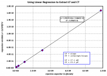
But if you really, really need to measure both L and Cinterwinding, Quasimodo Appendix C shows one way to do it. Measure resonant frequency with a variety of external capacitor values. Then perform linear regression. The slope gives you the inductance and the intercept gives you the interwinding capacitance.
But if you really, really need to measure both L and Cinterwinding, Quasimodo Appendix C shows one way to do it. Measure resonant frequency with a variety of external capacitor values. Then perform linear regression. The slope gives you the inductance and the intercept gives you the interwinding capacitance.
Attachments
Thanks to all for the excellent advice.
I think (and was initially doubtful) that using Q wouldn't be the best way to QC these coils, but a colleague came to me with this as his idea, then asked how to calculate Q....I said id work through the idea and see if it was really any use, whilst having some doubts.
Without going the route of DLA and TanDelta testing on top of usual tests there are many things that only inductance and Q measures will miss.
All the same, excellent help.and advice guys, so thank you very much indeed.
The best way to evaluate inductors or verify for production is to measure them in the conditions they will be used in. A bridge operating at 60 Hz or 1 KHz really will not tell you much about an inductor used for a switching supply running at 50 KHz. DCR if you have enough resolution will tell you how much wire is inside the part. Its not much help for anything else. There are instruments designed for accurate measurement of DCR of inductors. Many DVM's get confused by the inductance reacting to the current source. Big inductors are much harder to deal with because you need to know at what current they saturate and how the inductance changes with frequency.
A premium bridge can usually automatically determine the best way to measure an inductor. They can also measure inductace / loss etc. at different frequencies.
You could measure the self resonance of the inductor to see if the internal shunt capacitance has varied much from the reference.
Maybe a little more about the application, inductor size and operating frequency etc. will help focus on a solution.
Last edited:
If the test equipment budget can stretch to it something like the Wayne Kerr Electronics wound component analyzers are good. Wound Component and Transformer Tester - Wayne Kerr Electronics
Yes. Test under conditions not too far removed from the circuit operation.1audio said:The best way to evaluate inductors or verify for production is to measure them in the conditions they will be used in.
The inductor is presumably intended to carry out some function in a circuit, either adding impedance or coupling or both. Winding uniformity will not affect these much so probably not worth testing for. However, uniformity may affect temperature stability so you could check for that - time consuming, though!
Don't fall into the trap of thinking that Q means Quality in general - it does not. It refers to one very specific measure: how much energy is dissipated and how much energy is stored.
All,
Yes. I am familiar with resonant circuits (well familiar to degree level, if that means anything 🙂)
I have used 2 LCR bridges. Old Phillips meter, very good. Agilent hand held meter.
Both agree. Were talking 0.032 Ohms DCR, using a 10 Amp bridge; a L of 24.8mH , and Z of 158 Ohms @1kHz; Q of 4.8.
The series Rloss is 32 Ohms.
I am hoping to use the Q and L against design values to assess interwinding uniformity, or coil tightness (or relative slackness) and detect insulation losses out of spec, by virtue of an increase in Rloss and Q.
A standard production test is the impulse test. Charge a capacitor to some voltage, connect it to the inductor, and watch the waveform. For consistent inductors, the waveform will ring at the same frequency, and will decay at the same rate. A good machine will store the waveform of the master sample, and compare it to the tested one.
Another good thing about the impulse test, is that it looks for insulation integrity. My tester goes from 500 volts to 5 kilovolts. If the inductor needs to work with say, 1000 volts, I'd use 1200 to 1500 volts in the test. If the insulation is compromised, you can see arcing by waveform discontinuities. A short tosses the waveform totally.
You are seeing very high resistance numbers because the test frequency you are using is causing the current to crowd to the inner volume of the copper wire, this is proximity effect. It will be a very heavy function of frequency, and it takes off very quickly, I'll attach a graph from my gallery.
Sweep a good inductor through a wide range of frequencies, 20 hz to 1 Khz or so. You will get the exact same type of response I show in the graph.
Make sure you have no metal close to the inductor, as it will both change the inductance via lenz exclusion, and change the reported resistance via eddy dissipation. My gallery also has 3 smaller inductors which I tested in air and against a copper clad PC board to show the influence of the metal.
The numbers you report look consistent with the value of inductance you are measuring. Here is an inductor 1/5th the size of yours, you see how quickly it takes off resistance wise with respect to a comparable inductor would with litz.
litz vs solid copper air core inductor resistance vs frequency - My Photo Gallery
jn
Last edited:
A remarkable result indeed. Did you carry out such measurements with voice coils of loudspeakers yet?
Jn,
what wire diameter is the solid copper version?
How would the results look if a four wire version using half diameter copper turns? i.e. same copper area.
I have stock of 0.3mm and 0.4mm diameter enameled copper wire, that I am hoping to use for ~50kHz SMPS.
what wire diameter is the solid copper version?
How would the results look if a four wire version using half diameter copper turns? i.e. same copper area.
I have stock of 0.3mm and 0.4mm diameter enameled copper wire, that I am hoping to use for ~50kHz SMPS.
I measured one woofer, I think it was an eminence omega pro 18. I measured it with cone up, and with cone down on a really flat surface to get close to locked coil numbers. The real issue with vc inductance is that the motion confuses the meter. The meter does not know how to separate magnetic field inductance of a vc with the stored mechanical energy of the system. As such, low frequency inductance will rely heavily on the enclosure the cone is connected to.edit: don't forget, V = IR + Ldi/dt + Idl/dt. The inductance of a moving coil in a metallic sided gap is also frequency and velocity dependent. So the measurement, while easy to do using a meter, is the sum of some very hairily complex interactions.A remarkable result indeed. Did you carry out such measurements with voice coils of loudspeakers yet?
Metric...sheesh..Jn,
what wire diameter is the solid copper version?(the graph said 15 awg.)
How would the results look if a four wire version using half diameter copper turns? i.e. same copper area. (don't know, I did tests on a two wire version, but I'd have to find the data. It was a little better than the single conductor, but nowhere as good as the litz.)
I have stock of 0.3mm and 0.4mm diameter enameled copper wire, that I am hoping to use for ~50kHz SMPS.
22 awg? my gallery has 20 and 18, .3 mH roughly. If you put it on a toroid, it changes things considerably.
Your best bet for those questions would be Eva.
jn
Last edited:
It very much depends on the topology of the supply, and where it is used in that topology: for a transformer in a symetrical converter, 99.9% of the flux remains confined in the magnetic circuit, and using 0.4mm wire poses no particular problem, you just have to account for the (modest) increase in resistance caused by skin effect (and also in theory by the proximity effect, but that's more complicated).I have stock of 0.3mm and 0.4mm diameter enameled copper wire, that I am hoping to use for ~50kHz SMPS.
As soon as you use your wire in a component subject to a high reactive power, like a flyback transformer or the first filter choke in in a forward converter, the apparent permeability of the core needs to be reduced in order to be able to store energy, and this means eddy currents will begin to play a significant role.
That's where Litz wire might be necessary, the worst case being of course an air core coil, where there is no flux confinement at all. This causes the apparent increase in esr (in fact, physically it is a parallel type of loss, but paralleling a loss resistance with an inductor increases its esr, somewhat counter-intuitively)
jneutron has it
These coils are alternator rotor poles 🙂
A Q meter is routinely used to check for shorted turns
However, i am not certain i should include more detail (deliberately attempting to keep this vague for IP reasons)
Thanks for the advice, i think perhaps i should leave this idea.
These coils are alternator rotor poles 🙂
A Q meter is routinely used to check for shorted turns
However, i am not certain i should include more detail (deliberately attempting to keep this vague for IP reasons)
Thanks for the advice, i think perhaps i should leave this idea.
Last edited:
- Status
- Not open for further replies.
- Home
- Design & Build
- Equipment & Tools
- measuring inductors: expert advice wanted