Hi All,
I have begun measuring TS parameters on my 6 TB-871S and I am getting strange results from just the first pair.
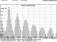
First I used the 1Kohm resistor Impedometer and got very distinct impedance plots with Fs = 139! and Zmax = 72 and 61. F1 = 118 and F2 = 164 . I used 8mv and an 8ohm calibration resistor. More Info Here
Next I tried the method at Rod Elliot's Site with the same drivers and got Fs = 121hz ,Zmax=43 ohms and F1 = 105 and F2 = 140 Here I used an 8ohm series resistor and used 600mv as the Vs.
In both cases the Z converged to Fs nicely and the "Sanity" checks worked correctly in both methods. My concern is that I am getting such radically different results from the two methods. I hope Rod's method its better but also in either case the calculated Qts is > 1.
I was using WinISD as a Signal Generator and my Frequency counter showed the exact value in WinISD so I was confident that the frequency was good.
The attached image is the first measurements with the 1K series resistor. I actually took over a hundred measurements per driver.
Any Ideas what I could be doing wrong? Are there better tests or is this just the case that one method is very small signal and the driver acts differently with different signal amplitudes?
Thanks,
Gregory
I have begun measuring TS parameters on my 6 TB-871S and I am getting strange results from just the first pair.
First I used the 1Kohm resistor Impedometer and got very distinct impedance plots with Fs = 139! and Zmax = 72 and 61. F1 = 118 and F2 = 164 . I used 8mv and an 8ohm calibration resistor. More Info Here
Next I tried the method at Rod Elliot's Site with the same drivers and got Fs = 121hz ,Zmax=43 ohms and F1 = 105 and F2 = 140 Here I used an 8ohm series resistor and used 600mv as the Vs.
In both cases the Z converged to Fs nicely and the "Sanity" checks worked correctly in both methods. My concern is that I am getting such radically different results from the two methods. I hope Rod's method its better but also in either case the calculated Qts is > 1.
I was using WinISD as a Signal Generator and my Frequency counter showed the exact value in WinISD so I was confident that the frequency was good.
The attached image is the first measurements with the 1K series resistor. I actually took over a hundred measurements per driver.
Any Ideas what I could be doing wrong? Are there better tests or is this just the case that one method is very small signal and the driver acts differently with different signal amplitudes?
Thanks,
Gregory
Attachments
Gregory,
Although I can't help you with your specific problem, I can suggest an alternative automated method! The Speaker Workshop software is free and uses your soundcard output to provide test signals and the line-in to measure the results. It is available to download here:
http://www.speakerworkshop.com
If you can't be bothered to make the full jig, there is a diagram on this page showing the cable connections to measure impedance and TS paramneters:
http://planeta.terra.com.br/educacao/claudionegro/english/swsetup/cables/cables.html
The software will produce an impedance plot of your speakers in a several seconds and can calculate the TS parameters using added mass or test box method. It can also do acoustic measurements although a microphone and, ideally, an external pre-amp is needed for this.
Nice one,
David.
Thanks David
I have speaker workshop and a few other programs that automate the process but I did want to try it manually first so that I understood how it worked. I have made the cables for the Jig's already and will try SpeakerWorkshop and others and post the results.
I still would like to know how others are manually measuring the T/S parameters and what accounts for the great difference in the results.
Gregory
I've had mixed experiences with measuring TS parameters and even started a thread about it here:
http://www.diyaudio.com/forums/showthread.php?threadid=9993
As Kelticwizard pointed out, differences in Fs and Vas figures tend to cancel when the driver is put in a box.
BTW, I was in Columbus recently (I work for Lucent) - such a shame about that factory...
http://www.diyaudio.com/forums/showthread.php?threadid=9993
As Kelticwizard pointed out, differences in Fs and Vas figures tend to cancel when the driver is put in a box.
BTW, I was in Columbus recently (I work for Lucent) - such a shame about that factory...
Small World
I saw that thead while searching but but I was concerned about Qts and not Vas. I hope to measure Vas tonight and I guess it might become clearer.
Do people just build speakers from the manufacturers specs?
I was in Bath (quite) a few years ago. I had tea at the Tea House. It is sad about the Columbus Factory, that was the old Bell Labs, I think.
Thanks Again,
Gregory
well having very good inside knowledge about the 871S
The FS is all around the 130 range.
Tested almost 100 to be sure.
The FS is all around the 130 range.
Tested almost 100 to be sure.
Well I used Workshop at that time but now have MLSSA.
You know what will fill these holes???
http://members.shaw.ca/awooley/pictures/SuperELFHT.JPG
Super ELF home theater system
I have them in a small encloser that goes out past 23k smooth as a babys bottom.Matched with the CSS driver.This will be a kit on the CSS site soon.
Will post the screen shot later .Wife has the Van now with them in it.
An externally hosted image should be here but it was not working when we last tested it.
You know what will fill these holes???
http://members.shaw.ca/awooley/pictures/SuperELFHT.JPG
Super ELF home theater system
I have them in a small encloser that goes out past 23k smooth as a babys bottom.Matched with the CSS driver.This will be a kit on the CSS site soon.
Will post the screen shot later .Wife has the Van now with them in it.
Maybe you've posted it elsewhere RAW but at what point do you crossover the 871S in your super elfs? I ask because I have a similar project with a 871S crossed over to a much larger woofer, but it is a dipole, much more complicated (dipole eqing) but in nature still very much the same, relying on the TB to produce excellent sound.
Also, did you CNC all those boxes? If not that must have been alot of time. Either way I really admire your work, your ability to produce a product that most likely sounds excellent (I've heard the 871S, I know why you like them so much) and at a very reasonable price (CSS sells the original elf kit at a price that allows anyone to have hi-fi), is really a great thing.
Also, did you CNC all those boxes? If not that must have been alot of time. Either way I really admire your work, your ability to produce a product that most likely sounds excellent (I've heard the 871S, I know why you like them so much) and at a very reasonable price (CSS sells the original elf kit at a price that allows anyone to have hi-fi), is really a great thing.
No I have not posted the design as it a CSS design I did for him.
As well as the 2.0 design that is a 4th order using the CSS design.
CNC was done on the fronts and backs only.I cut all other pieces and assembled them.
The CNC does the best amount of scalloping for the 3" drivers.
Look at the ELF page on my site and you can see the inside of the baffles.
Yet leaves a post to have for screws to mount the 3" drivers.
I am going to install the TB line of 3" models I have on hand in the 1.0 cabinet and then the 1.5 using the Elf 1.5 filter in that model.And shoot MLSAA responces with all the 3" drivers from Nuera and PE at this time.
This I will get to after vacation for Bob.
Al
http://members.shaw.ca/awooley/pictures/45mitercorner.JPG
gregorx said:Hi All,
I have begun measuring TS parameters on my 6 TB-871S and I am getting strange results from just the first pair.
First I used the 1Kohm resistor Impedometer and got very distinct impedance plots with Fs = 139! and Zmax = 72 and 61. F1 = 118 and F2 = 164 . I used 8mv and an 8ohm calibration resistor. More Info Here
Next I tried the method at Rod Elliot's Site with the same drivers and got Fs = 121hz ,Zmax=43 ohms and F1 = 105 and F2 = 140 Here I used an 8ohm series resistor and used 600mv as the Vs.
Gregorx,
I don't see anything particularly disconcerting with your measurements. Measuring T/S parameters of a driver can be a rather difficult thing to do, as it's GREATLY dependent on drive level and test setup. You've got a 17% drop from the first to second measurement...so, do you know what the tolerance of your resistor was? What about any frequency dependance in your multi-meter? What else did you change in the testing process? How the woofer was mounted for test? Was it pointing up in one test (towards the ceiling) and horizontal for another. All of these can come into play.
The difference between the two different methods don't bother me at all, and I don't see them as all that large. I use LAUD for my measurements and it took me about 20 hours of experimenting to come up with a measurement method of how to mount the driver, the best way to add mass, to know to experiment with drive levels and such. (The Dr. D'Appolito was nice enough to publish his book and put most of that information in there...about a month later. Grrrr.) Since then I have tested A LOT of drivers.
TB drivers have always come into my shop and onto my desk and measured pretty darn close to the published specs. I'm sure there are some exceptions but not in the drivers I've measured. In fact in many cases they are closer to factory specs than their more expensive European counterparts. (I'm not saying they are better than the usual suspects, just that the T/S parameters measure closer to factory specs.) So, if you want to design a bass alignment based on factory specs, go ahead. Make your box slightly large and play with tuning and box volume. That way you can make a bass alignment you like most.
For grins, I've attached an intermodulation plot for a Tang Band 4" woofer....135Hz, 150Hz, and 165Hz, the volume level was adjusted for 96dB at 1 meter, but measured nearfield, so ignore the absolute scale. The relative levels of distortion are unaffected however.
Scott
Attachments
Well I can tell you a few things about the FS on some TB models.
25-302S
Tested over 50 of them FS from 1500-2200K yes
28-847S tested over 40 ran out at 850k -2100k
W3-593S Ran out at 135 average
W3-871S same as above in the love 130 range
W4-657S tested 40 unites all in the 75+ range
W5-705
W6-789S
W8
Well you get the idea I think.
The tweeters are the worst for consistancy that is for sure over 1" they all test out very close but not as published that is for sure.
Al
I've only tried the 2" and above drivers. I've never thought seriously about using the 1" dome drivers since I've heard so many stories of inconsistency in them.
Everyone I've ever talked to has only had good things to say about build quality and consistency in the larger drivers. My experience, and yours certainly seems to confirm that. For budget drivers they do very well.
Scott
Everyone I've ever talked to has only had good things to say about build quality and consistency in the larger drivers. My experience, and yours certainly seems to confirm that. For budget drivers they do very well.
Scott
ya
Scott .
The price and performance is just nuts for the TB line.
The New 4" modles look interesting as well.
Just who gets them first.PE or Nuera.
The Sleeper is the W5 from Nuera.Killer 5" driver and built like a tank.
I have them in a MT and MTM using the 871S at this time as well as the W6-789S going into a tall tower tuned out at 45HZ using the G2 ribbon .
Al
More on Methods
Hi Scott,
Thanks for your reply. I used a Mic Stand to hold the drive in the center of the room and the driver was facing forward as it would normally be in an enclosure. For each test all things were constant except the jigs.
The first method used 8mv which is about the lowest signal that my rather new multimeter can read. It is not a true RMS meter so I am not sure what it does read. Does it approximate RMS or read Peaks? I don't know. It is a ~$100US fluke. This could be something.
The second method used 600mv which is quite a big difference in voltage and I suspect that the increased signal accounts for the difference in Fs but do drivers have a different Fs depending on the amplitude of the signal?
I checked the resistor (a 100W 8ohm non-inductive load) and moved the frequency of the signal generator around while calibrating the methods. Neither the amp (Alesis), multimeter or resistor seemed to be frequency dependent in the range of Fs or two octaves above.
For the 1K resistor in the first method I just used a standard carbon brown resistor.
Gregory
SpeakerWorkShop
I attempted to use SpeakerWorkshop method but the machine in my shop has Yamaha Digital Studio cards and Yamaha Synth cards that are not standard in the least and barely do multimedia so after many attemps at adjusting the signal level I have decided to test them at my regular desktop which does have a standard crystal sound card. I will post the results if it works.
Speaker workshop is not very friendly when it comes to calibration and level adjustment and the site that David mentioned was very helpful. I also found this Site that also proved helpful.
Results forthcoming I hope.
Gregory
Re: More on Methods
How firmly is the driver clamped? There are some that say it should be suspended and allowed to swing freely, but I have NEVER gotten good results with this. It should be clamped firmly in such a way that the cone is pointing towards a wall. The clamping method should hold the driver SOLIDLY, but allow free airflow out the back or pole piece vent.
It's VERY VERY difficult to accurately measure signals in the 8mV range with a multimeter, or an oscilloscope. I wouldn't use this test method ever because of just this reason alone.
There is almost a factor of 100 between the two test levels you used. There will certainly be a shift downward of FS due to this level difference.
I've shifted driver FS down by 10, 20 and even 30% due to drive level differences. (There was this really stiff suspension car woofer that went from 50Hz cold, and low level signal to 30Hz with a higher level signal after it had been excercised for a while. You could then measure the woofer at a low level signal and get ~35 Hz...FS...on line with the specs. Leave it alone for a few hours and try again...right back to 50Hz. )
Try again with SW and let us know how it works out. I'll see if I can't dig up a pic of my testing setup, or set it up and take a new pic.
Scott
gregorx said:Hi Scott,
Thanks for your reply. I used a Mic Stand to hold the drive in the center of the room and the driver was facing forward as it would normally be in an enclosure. For each test all things were constant except the jigs.
The first method used 8mv which is about the lowest signal that my rather new multimeter can read. It is not a true RMS meter so I am not sure what it does read. Does it approximate RMS or read Peaks? I don't know. It is a ~$100US fluke. This could be something.
The second method used 600mv which is quite a big difference in voltage and I suspect that the increased signal accounts for the difference in Fs but do drivers have a different Fs depending on the amplitude of the signal?
I checked the resistor (a 100W 8ohm non-inductive load) and moved the frequency of the signal generator around while calibrating the methods. Neither the amp (Alesis), multimeter or resistor seemed to be frequency dependent in the range of Fs or two octaves above.
For the 1K resistor in the first method I just used a standard carbon brown resistor.
Gregory
How firmly is the driver clamped? There are some that say it should be suspended and allowed to swing freely, but I have NEVER gotten good results with this. It should be clamped firmly in such a way that the cone is pointing towards a wall. The clamping method should hold the driver SOLIDLY, but allow free airflow out the back or pole piece vent.
It's VERY VERY difficult to accurately measure signals in the 8mV range with a multimeter, or an oscilloscope. I wouldn't use this test method ever because of just this reason alone.
There is almost a factor of 100 between the two test levels you used. There will certainly be a shift downward of FS due to this level difference.
I've shifted driver FS down by 10, 20 and even 30% due to drive level differences. (There was this really stiff suspension car woofer that went from 50Hz cold, and low level signal to 30Hz with a higher level signal after it had been excercised for a while. You could then measure the woofer at a low level signal and get ~35 Hz...FS...on line with the specs. Leave it alone for a few hours and try again...right back to 50Hz. )
Try again with SW and let us know how it works out. I'll see if I can't dig up a pic of my testing setup, or set it up and take a new pic.
Scott
Hi All,
Thanks for all the help on this. I have successfully measured the free air impedance of all six drivers using SpeakerWorkshop see attached picture. The numbers on the drivers are the serial numbers.
This method, in comparison to the two manual methods that I used before was of course much easier and interestingly provided Fs results very similiar to the Impedometer. The average Fs for the six drivers (all from the same production batch) was 140hz. The big difference between this automated method and the two manual methods is the actual impedance at Fs which was around 120 ohms in contrast to the 43 and 72 ohms of the other two methods.
Still with this method the Qts are very high ~1.
I will build the Sample Test box today. According to the Weem's Book the standard box should be 8"x8"x5". Does this sound correct?
Attachments
- Status
- Not open for further replies.
- Home
- Loudspeakers
- Multi-Way
- Measuring Drivers TB-871S - Help!