Here's the circuit I used -- WJ's updated for the SSSM2019.
Having blown up many SSM2019's it would appear to make sense to have the ability to precharge the capacitors!
An externally hosted image should be here but it was not working when we last tested it.
Having blown up many SSM2019's it would appear to make sense to have the ability to precharge the capacitors!
I'm unclear what it is that is "not so". Your findings don't appear to contradict what I said.tvrgeek said:I modeled a dozen or so two-device CCSs and I would say this is not so. Yes, the device selection is important as you can make the best circuit poor with a bad choice, but the topology seemed to have a large effect on the impedance over frequency and it was the primary driver of basic stiffness.
I think I mean
"Fortunately, linearity and high impedance are not necessarily enemies as being really good at one means you don't have to be quite so good at the other."
I have not been able to reconcile to get both. It comes back to which sounds better, a self biased FET at -95dB but flat beyond the BW, or something much stiffer, like a BJT/FET cascode at -135 but dropping fast above 10K? The middle ground of a feedback pair that is still slightly stiffer than the JFET at 20K, but much stiffer across the lower freq. Ref: In my model a resistor is about -60 dB.
I think we are talking about two different things. I said 'linearity', not 'flat frequency response'.
High CCS impedance works against flat frequency response, as a given parallel capacitance will have a greater effect on a higher impedance CCS.
High CCS impedance can offset the effect of nonlinearity, as a nearly-infinite impedance can be almost as non-linear as you like without harm. Perhaps there may be a requirement for no hysteresis too.
Ale: Try this -- you won't blow up your signal generator --
It's basically a HV inverting amplifier --
because the MOSFETs have reactive components you have to make a measurement with Z=R(real) for a baseline of magnitude and phase, then take the measurements with the device under test and use complex algebra to calculate the reactive impedance. Audio Precision has a macro for this on their website written in the AP version of VBasic.
An externally hosted image should be here but it was not working when we last tested it.
It's basically a HV inverting amplifier --
because the MOSFETs have reactive components you have to make a measurement with Z=R(real) for a baseline of magnitude and phase, then take the measurements with the device under test and use complex algebra to calculate the reactive impedance. Audio Precision has a macro for this on their website written in the AP version of VBasic.
Thanks Jack for the suggestion!
Quick question, what if I measure input voltage at output of Q2 and then across the sensing resistor at the output of the CCS? Wouldn't I avoid this way the impact of the HV amplifier?
Thanks
Ale
Quick question, what if I measure input voltage at output of Q2 and then across the sensing resistor at the output of the CCS? Wouldn't I avoid this way the impact of the HV amplifier?
Thanks
Ale
Ok. So here is what I'm planning to test. First the circuit for CCS measurement:
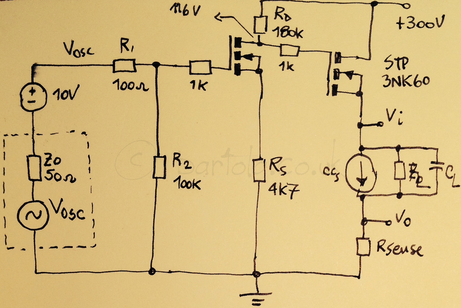
This will work fine I suppose. The gain is about 40(32dB) and should deliver 120Vpp to the CCS. I could measure then 115dB with averaging on the oscilloscope or with the PC audio interface. With a single supply the CCS current will pass through the sensing resistor and I wouldn't be able to use my 60dB differential preamplifier. Any ideas to avoid this?
I guess I could use a similar arrangement as the one shown below which I was planning to use for measuring choke inductance (or transformers):
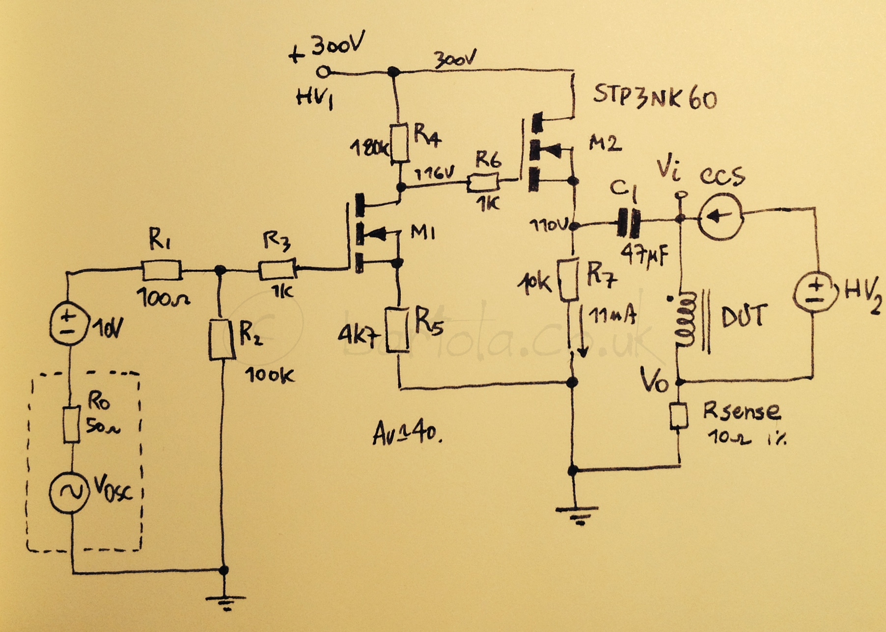
This way the load current doesn't go through the sense resistor. It requires a second power supply as a downside.
thanks
Ale
This will work fine I suppose. The gain is about 40(32dB) and should deliver 120Vpp to the CCS. I could measure then 115dB with averaging on the oscilloscope or with the PC audio interface. With a single supply the CCS current will pass through the sensing resistor and I wouldn't be able to use my 60dB differential preamplifier. Any ideas to avoid this?
I guess I could use a similar arrangement as the one shown below which I was planning to use for measuring choke inductance (or transformers):
This way the load current doesn't go through the sense resistor. It requires a second power supply as a downside.
thanks
Ale
- Status
- Not open for further replies.
- Home
- Design & Build
- Equipment & Tools
- Measuring CCS impedance