I watched a video that made me reevaluate life's meaning..
Well, not really lol.. But, it sure confused me on how B+ should be measured for figuring tube bias on a 300B.
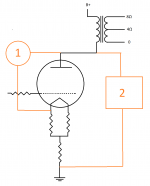
The attached shows my dilemma.
I assumed B+ should be measured from #2... After the video, I now think #1 might be (EDIT: I mistakenly said wright) wrong
May be the cathode resistors are lifting the entire tube enough above ground, that the plate might not know (or care) about the voltage #2 measures (bird on a wire).
Before I make any more assumptions, I figured I should just ask the experts!
Well, not really lol.. But, it sure confused me on how B+ should be measured for figuring tube bias on a 300B.
The attached shows my dilemma.
I assumed B+ should be measured from #2... After the video, I now think #1 might be (EDIT: I mistakenly said wright) wrong
May be the cathode resistors are lifting the entire tube enough above ground, that the plate might not know (or care) about the voltage #2 measures (bird on a wire).
Before I make any more assumptions, I figured I should just ask the experts!
Attachments
Last edited:
Between cathode and ground you will measure Bias potential.
Between anode (plate) and cathode you will measure the Anode voltage.
In normal cases (No grid current or very little) between grid and ground you will measure almost no voltage.
In any case, those voltage without signal. Plate voltage under certain circumstances may have large voltage spikes that can deteriorate any digital instrument, under some large signal input conditions. I suggest to read elsewhere about Thevenin's Theorem and the Kirchhoff's Laws. They are easy to understand (Common sense) and very important.
Usually "plate voltage" means the plate-to-cathode voltage. So option 1. That's the voltage that's relevant for the tube.
The other relevant voltage is the grid-to-cathode voltage. Assuming zero grid current (and a grounded grid) you can find -Vgk as the voltage across the cathode resistor.
Tom
The other relevant voltage is the grid-to-cathode voltage. Assuming zero grid current (and a grounded grid) you can find -Vgk as the voltage across the cathode resistor.
Tom
Thank you Tom!
I wrote this before I saw your reply....
So, I really appreciate every ones help, I really do.
While the responses may make perfect sense to most, and my question may have been answered twice, call me dense, but none have said "B+ should be measured for figuring tube bias on a 300B at point ____ (1 or 2 or 3)"
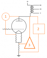
The first response "between anode and 3 resistors" from my drawing I thought would have been #2 in my image, but euro21 said #3 lol. The 2nd response still did not say exactly what I need to hear (again thick headed). As the 300B shares the heater and cathode, the only place to get a measurement without shorting the heater supply would be #3.
The video showed #1 (or pin 1), but that leaves the other heater, or pin 4 unaccounted for.
I ask, as the my measurement from 1 and 2 are worlds apart. For me, #1 is 380v and #2 is 450v.
I wrote this before I saw your reply....
So, I really appreciate every ones help, I really do.
While the responses may make perfect sense to most, and my question may have been answered twice, call me dense, but none have said "B+ should be measured for figuring tube bias on a 300B at point ____ (1 or 2 or 3)"
The first response "between anode and 3 resistors" from my drawing I thought would have been #2 in my image, but euro21 said #3 lol. The 2nd response still did not say exactly what I need to hear (again thick headed). As the 300B shares the heater and cathode, the only place to get a measurement without shorting the heater supply would be #3.
The video showed #1 (or pin 1), but that leaves the other heater, or pin 4 unaccounted for.
I ask, as the my measurement from 1 and 2 are worlds apart. For me, #1 is 380v and #2 is 450v.
In practice, many folks will measure from anode to signal ground, and again across the cathode bias resistor, and just subtract. This gives you the bias voltage too, and lets you keep one hand in your pocket - especially important when getting started. 450 Volts hand-to-hand is no joke - some folks even die.
All good fortune,
Chris
All good fortune,
Chris
I recommend what Chris suggests, both because it gives you a reasonably accurate value and because it is safer.
Thank you Tom!
While the responses may make perfect sense to most, and my question may have been answered twice, call me dense, but none have said "B+ should be measured for figuring tube bias on a 300B at point ____ (1 or 2 or 3)"
That's because B+ in itself doesn't determine tube bias. If you back up a bit you'll note that they explain that tube bias is determined by Vgk.
B+ is simply the power supply voltage and is normally measured against ground.
Jan
Last edited:
So option 1.
... if the tube is indirect heated and has cathode.
In case of direct heated tubes between anode and filament the static voltage is different if you change the measuring point between filament ends.
In the picture the DHT tube has two -small- resistors, which have a common point: the virtual cathode.
This is the measuring point.
Ahh, I see.. I misspoke when I used the term B+. Now its clear. What I wanted was plate voltage. The comment by Chris now also makes perfect sense and is crystal clear.
With no input signal, my cathode resistor voltage drop was 71/72 volts (1.05KΩ) for 68mA.
I measured the voltage from the plate (pin 2) to Pin 1 and measured 376/380
While my B+ is 450v, the plate voltage is about 376v. (376+71 close enough to the 450v)
I also measured the DCR on my OPT and had 262Ω with a voltage drop of 18.7v, works out to 71mA, close enough to the 68mA ?
It now strikes me, that looking at the tube characteristics charts for the 300B that Ec IS pretty much the current through my cathode resistor??? If so, the Ah HA moments are piling up today lol...
Looking at various tube characteristics charts, I think, if I wanted to dial the bias in a little more, the cathode resistor ideally should have about an 80V drop, but that would also change the plate current. Time to hit LTSpice...
Is there is a faster way to figure this ratio out or am I close enough ?
You are close enough, this is a good operating point for the 300B.
I run them with 400V on the plate and fixed, not cathode bias, at 65 - 75mA Grid bias is in the -68V to -75V range depending on tube and set plate current.
I've built a lot of 300B amps over the years.
I run them with 400V on the plate and fixed, not cathode bias, at 65 - 75mA Grid bias is in the -68V to -75V range depending on tube and set plate current.
I've built a lot of 300B amps over the years.
Fantastic, now to move on to solving another small issue that popped up.. quick and dirty is, putting local feedback on a switch has caused a small amount of additional gain. With the volume down as far as it can go, enough signalbhet through.. to keep the threads tidy, I will post when I have enough info .. Thanks to all!
Umm, that sounds like positive feedback to me.. The open loop gain is probably low enough that it is not enough to make the amplifier oscillate, but if applying feedback makes it louder then that is what is going on. You can swap the connections to the secondary (only swap the primary connections if you are sure you wired them backwards - in an ideal transformer this would not matter, but in real world transformers the end near the core generally has a bit more capacitance than the far end which may affect HF response)
Umm, that sounds like positive feedback to me..
Kevin, from what I understand, negative feedback feeds a tiny inverted signal back to the input. This reduces the gain but also reduces distortion and harmonics.
In my amp, with negative local feed back as normal, the output is lower.
A signal in, with the volume down all the way produces no sound.
With negative local feed back off, the output of the stage before the 300B is higher. With a signal, and the volume knob down, U can hear music slightly.
I have a hunch, the best way to mange this might simply be on the other end of my toggle an unused. While the local negative feedback is off, I can also introduce another resistor in parallel with the screen resistor to allow slightly more directly to ground...
Maybe a pot issue? I assume that it is not a wiring issue. I recommend upgrading to a stepped attenuator if that is not already what you have.
Can you post your amplifier circuit. I am not sure what you mean when you mention screen.
Can you post your amplifier circuit. I am not sure what you mean when you mention screen.
- Home
- Amplifiers
- Tubes / Valves
- Measuring 300B plate voltage