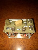
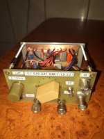
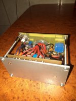
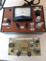
I think that the resonant series method is the safest method of measuring an inductor because it does not depend on the voltage level applied by that I made this device with 7 capacitors selectable between 0.1-2.2 microfarad and with the possibility of injecting dc current into the inductor by means of a CCS with setable current 0-100mA ,what do you think, Thanks
Attachments
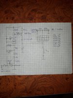
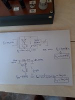
HOW you build it is a bit irrelevant. The schematic is where the beef is.
Jan
Jan

I'm not sure that is a valid statement. I'd suggest that if you change the test voltage level applied to the inductor as part of the resonance frequency measurement then you would find that the resonance frequency shifts. As such, the technique is only repeatable by others if you state the voltage applied to the DUT.I think that the resonant series method is the safest method of measuring an inductor because it does not depend on the voltage level applied by that.
Thanks for sharing it, but for completeness please post the schematic and a description of your measurement method.
Yes, injecting DC makes it a more realistic test, most LCR meters do not.
Yes, injecting DC makes it a more realistic test, most LCR meters do not.
I find simple series resistance test to be the most accurate, where you can easily control excitation voltage. I use values up to stabilized 100Vrms 50Hz.
The 50% voltage point? For a quick and dirty low excitation, no DC impedance check the DATS tester works well and provides 20Hz to 20kHz results.series resistance test to be the most accurate
You're right, I gave the generator voltages from 100mv to 7v and the resonant frequencies were different accordingly and the calculated inductances were different. Additionally, I injected a current of 50 me in the same conditions given from the generator and the results are visible in the measurement table, thanks for the warningI'm not sure that is a valid statement. I'd suggest that if you change the test voltage level applied to the inductor as part of the resonance frequency measurement then you would find that the resonance frequency shifts. As such, the technique is only repeatable by others if you state the voltage applied to the DUT.
Attachments

Thanks.
Clearly measurement with some DC current imbalance is the realistic way; perfectly pure AC is "optimistic" and varies a lot.
As always, measurement rules 😉
Clearly measurement with some DC current imbalance is the realistic way; perfectly pure AC is "optimistic" and varies a lot.
As always, measurement rules 😉
The 50% voltage point? For a quick and dirty low excitation, no DC impedance check the DATS tester works well and provides 20Hz to 20kHz results.
Just simple voltage excitation using a stabilized Vac source, series resistor and trueRms DIMM. It's mostly useful when I need to sort a batch of C-cores by permeability and measure primary inductance. My tool consists of an adjustable frequency generator driving an LM1875 amplifier driving a generic reverse wired power transformer with known parameters. And an excel sheet does the rest.
I have a OWEN DIY type of measuring axle inspired by the documentation provided by Steve Bench, an RLC Phillips PM6304 bridge, an L-meter that detects equality R and Xl all DIY plus a classic ESCORT type L-meter, without exception all give information on the inductance voltage function and measurement frequency of that I think there is no method of measuring the inductance in absolute values, however I wonder how the inductance of OT measures the reputed companies that produce such transformers
I guess reputed commercial companies must measure them in a way quite similar to yours.
Either resonant frequency or maybe more straightforward by using the 50% impedance drop and extrapolating from that.
Either resonant frequency or maybe more straightforward by using the 50% impedance drop and extrapolating from that.
Your absolute measurement accuracy would be a combination of frequency resolution and capacitance accuracy, and so could easily be out to +/-10%, but not such an issue for relative measurements.
One relatively simple way to improve diy accuracy of those two parameters is to use a soundcard and software (like REW), along with an REW impedance measurement setup. As an example, I confirmed the frequency measurement of my soundcard was within 0.0011% tolerance using a GPSDO, and could reliably measure L and C to better than 1% using a 0.1% tolerance resistor during REW calibration.
I typically use a different measurement technique for chokes with DC current ( https://www.dalmura.com.au/static/Choke measurement.pdf ), so that could be a convenient diy path for cross-comparison.
Interesting link provided by trobbins and it seems that the different methods of measuring an inductanct will give different results even if the frequency and voltage applied to the inductor will be similar
I also use RDH measurement method.
https://www.diyaudio.com/community/...-measure-l-under-dc-bias.297770/#post-4852990
See post #3.
https://www.diyaudio.com/community/...-measure-l-under-dc-bias.297770/#post-4852990
See post #3.
IMHO:
You don't want to know the inductance. You want to know the bass cutoff. Which depends on many things: the tube(s), the NFB.... for a single prototype you can build it and try it. Both ways: small signal (traditionally 1Watt for hi-fi sized amps) and near full power (so monitor THD not just dB).
You don't want to know the inductance. You want to know the bass cutoff. Which depends on many things: the tube(s), the NFB.... for a single prototype you can build it and try it. Both ways: small signal (traditionally 1Watt for hi-fi sized amps) and near full power (so monitor THD not just dB).
Still -- it is a lovely build.
But then, the bunch of you fine folks are a lot sharper than me . . 😉
Regards
But then, the bunch of you fine folks are a lot sharper than me . . 😉
Regards
Last edited:
I have an L-meter that works identically to the one presented by trobbins in the post #13 i.e. compare the voltage on a resistor R with the inductive reactance of the inductor. For practical reasons it was chosen the value of the measurement frequency equal to 159.6 Hz for an easy conversion 1K =1H the alternating voltage applied to the inductor is 1.5v and resulted in the R/Xl equilibrium a value of 30.7. By the resonance method we forced the choice of a capacitor of 32.9 nF so that the resonance is 158 HzSo the two methods give identical results if the frequency and the voltage applied to the inductor are identical. In addition, we injected 50mA in the two cases and the inductance value dropped to 21H and 21.4H respectively, which is a normal situation. Probably by extrapolation you can check other methods, what do you think
Attachments
Last edited:
Is it possible to put a bias current on the DUT and use a largish blocking capacitor on the test probes or does that mess up the measurement?The 50% voltage point? For a quick and dirty low excitation, no DC impedance check the DATS tester works well and provides 20Hz to 20kHz results.
That should post have been clearer. Every attempt to measure an OPT's primary inductance with the DATS system failed with a 'this doesn't look like an inductor' message. Where it's really handy is measuring effective primary impedance with an appropriate load on the secondary. Examples using two primary taps of a James JS-6123HS SE OPT attached. Note the vertical scale is kilohms.
Attachments
- Home
- Amplifiers
- Tubes / Valves
- Measurement of OT inductance by series resonance method