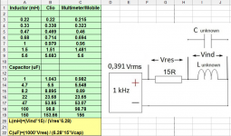
Inspired by Mark Johnson's suggestion in post #33 of Unmarked Iron Core Inductors thread to drive a measurement jig with a smartphone, I've conducted a couple of experiments to find out the combination of output voltage and series resistor needed to measure L and C values accurate enough to be of some use to DIYers. I used a 1 kHz sine signal at 0dB, converted it to mp3 file and saved to a phone, then adjusted the volume to maximum for this way the results matched Clio measurements as close as possible. The error seems to be about 2 percent on average. Phone's output impedance measured 2,15 ohms.
Attachments
Last edited:
I suspect (and plan to try) that an LRC series circuit would be even more accurate by adjusting for a null esp if the series R is smallish.
There are two conflicting design goals: (1) don't load your smartphone's output jack with less than ~ 16 ohms of Magnitude_Of_Impedance; (2) select the known impedance such that the voltage across the Known, is approximately equal to the voltage across the Unknown impedance. Goal (2) maximizes the signal-to-noise ratio of the measurement.
BTW a parallel LRC circuit is easier than a series LRC, if constrained by the finite-Z, nonzero-C oscilloscope inputs that God has given us.
BTW a parallel LRC circuit is easier than a series LRC, if constrained by the finite-Z, nonzero-C oscilloscope inputs that God has given us.
Last edited:
- Status
- Not open for further replies.