I just finished re-caping a pair of MC-60's for a buddy and one of them also had a problem once hot where it would low frequency oscillate. The speaker would just slowly move in and out about 1Hz. I put it on the oscilloscope and noticed the bottom wave form would clip way before the top so figured I better check the voltages. Turns out the clipped wave form was just a crappy tube but....
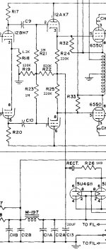
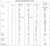
I downloaded the schematic and voltage chart. Everything tests right on spec except pin 2 and 7 on the last 12AX7. The chart shows -45V and I was showing -22 . So I figure the bias supply is shot so I rebuild it from the cap C13 and replaced the old rectifier with a diode. I replaced R21, R23 and R22 thinking these must be the culprits. Powered back on and exactly the same thing. Well 4 volts lower as I have not adjusted R26 yet. I cannot figure out how this is possible. Pin 3 and 8 on the 12BH7 test fine as with pin 3 and 8 on the 12AX7, what else is there that could be changing the bias? So I checked the other mono block and its exactly the same. Am I missing something or is this a mistake on the chart. The did change the schematic for the MC60 later maybe they did not change the voltages. I attached the chart and schematic, any input would be appreciated.
I downloaded the schematic and voltage chart. Everything tests right on spec except pin 2 and 7 on the last 12AX7. The chart shows -45V and I was showing -22 . So I figure the bias supply is shot so I rebuild it from the cap C13 and replaced the old rectifier with a diode. I replaced R21, R23 and R22 thinking these must be the culprits. Powered back on and exactly the same thing. Well 4 volts lower as I have not adjusted R26 yet. I cannot figure out how this is possible. Pin 3 and 8 on the 12BH7 test fine as with pin 3 and 8 on the 12AX7, what else is there that could be changing the bias? So I checked the other mono block and its exactly the same. Am I missing something or is this a mistake on the chart. The did change the schematic for the MC60 later maybe they did not change the voltages. I attached the chart and schematic, any input would be appreciated.
Attachments
Pin 3 and 8 on the 12BH7 test fine as with pin 3 and 8 on the 12AX7, what else is there that could be changing the bias?
The internal resistance of your voltmeter?
Jan E.
Pins 2 and 7 of the 12AX7 are fed by 1M resistors and the internal meter resistance is likely loading it down. (I bet it has a 1M input resistance if it is the typical DVM)
Last edited:
Measure at the junction of R21 and R23 to ground. The grids draw no current, it should be the same.
Thanks,
I understand what you are saying, I never thought of that I assumed the sheet gave the voltages and that is what they measured at. I will give it a measure at the junction when I get home from work.
I understand what you are saying, I never thought of that I assumed the sheet gave the voltages and that is what they measured at. I will give it a measure at the junction when I get home from work.
- Status
- Not open for further replies.