Hello!
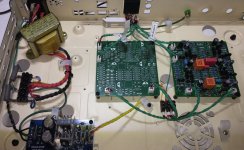
I'm in the building phase of my 42-transistor/channel rega elicit phono stage clone, currently built and testing one channel in the MM configuration only. Let me tell you I'm getting quite good at soldering TO-92 packages 😎
I'm getting gain in spades - A good omen for the MC configuration but I'm wondering if is a good thing in MM mode. I get a solid 2V pk-pk average with a 5mV cartridge input and that's after reducing gain a bit from the original design out of concern for loud click and pops. There doesn't seem to be any signs of clipping on the scope though.
What are the considerations in choosing a target output voltage, what is better S/N wise, any risks of coupling capacitor blocking?
The preamp picks up hum when sitting on my spare/test amp whose power transformer is exposed through vent slots but there is no hum on my basement setup amp that has a closed enclosure and is grounded to mains, even when listening through electrostatic headphones.
The MC gain is largely independent of the MM gain and set via paralleled resistors inserted in the input stage emitter circuit through dip switches (see pdf below for full schematic). I even have a higher MM sensitivity setting through a parallel resistor in the 100R range inserted with a position on that dip switch.
Thanks in advance for any insights. I would also like to thank everyone who helped me in this project, if you look at the original thread below you will see that when I started it I didn't even fully understand the basic blocks of the original amp and now look at me. A special shout out to @MarcelvdG and @EdGr who basically took me by the hand throughout - You guys are great!
-Joris
Schematics from the original thread
Attachments
Last edited:
The measured output is 0.7V RMS which is very close to the nominal line-level 0dB reference of 0.775V. I presume you are playing a test record and the cartridge is producing 5mV RMS at 1KHz.SomeJoe said:I get a solid 2V pk-pk average with a 5mV cartridge input
I computed the gain of the pre-amp at 37dB at 1KHz with all switches open. This is close to the nominal value of 40dB.
Ed

I don't have a test record. I jury-rigged a voltage divider off the output of my cheap signal generator that can only go down to 100mV, to get a 5mV 1Khz sine although with a lot of noise. Also listened to a regular well mastered record. I think I will build a reverse RIAA generator as a side project.I presume you are playing a test record and the cartridge is producing 5mV RMS at 1KHz
What is your S/n on this pre?
How does it sound?
Simple solution is a 10k pot on the output to match levels on your amp.
Changing the feedback resistor may change the overall response curve.
How does it sound?
Simple solution is a 10k pot on the output to match levels on your amp.
Changing the feedback resistor may change the overall response curve.
Unknown at this point - I'll check if I can measure it with my limited equipment. As for the sound, that is where the "well mastered record" comes into play, to evaluate by ear the audio spectrum. Everything seemed to sound like it should, I didn't get too much or too little of bass and mids/highs so the RIAA eq looks correct.What is your S/n on this pre?
I have put back the 20R input emitter resistor, made more precise measurements feeding a 4 mV 1KHz sine and the output was indeed spot on at 40 dB.
I also finished the MC configuration section. The resulting gains are as follow:
- With 4R7 resistor : 51.5 dB
- With 2R7 resistor : 54 dB
- With 4R7 and 2R7 resistors paralleled : 57.5 dB
57.5 dB brings the 0.3 mV Denon DL-103 to about 225 mV. Seems a bit low, we'll see during tests with the actual TT this weekend.
Touching wood as to the hum immunity of the unit in MC mode as I built it as a worse case scenario using steel chassis and EI power transformer. It wasn't a problem for MM as mentioned above.
Last edited:
I think 43dB - 2V peak-to-peak v. 5mV rms input, not 2V rms v. 5mV rms.... Confusing to mix measurements like this (and I am assuming the 5mV is the standard rms and not peak).That is 52db of gain. 40 to 45 is more typical for MM.
35dB gain at 1kHz is a plausible value - then 50mV rms in gives 3V rms which probably won't clip in normal design (+/-15V). 45dB is risky for overload on a hot cut.
Mine is a little higher 48 dB at 1 khz. I put a high filter at 30khz between 1st and 2nd stages and see no pops anywhere close to clipping.
I used a single transistor as 1st stage op amp as 2nd.
I used a single transistor as 1st stage op amp as 2nd.
Friends, I'm happy to report a success after hooking up to the MC cartridge in my main setup.
Even with the enclosure top removed for testing the dip switch settings there is no noticeable hum and the noise floor is barely audible when listening through electrostatic headphones. As can be expected the noise floor is slighly higher at the higher gain setting; overall noise is less than the original amp's.
Since the preamp was connected to the amp whose phono section is the source of this cloning project I could compare both. Gain is about the same as the original circuit, and adequate even at the lower sensitivity setting. The clone seems to actually sound a bit better. This may be due to fresh parts or builder euphoria but I might very well end up using the clone over the amp's phono section. I didn't even broke up the low noise and audiophile parts box yet 😎
If someone stumbles on this schematic please note that there is an error, R259 (100R) is not supposed to be in the input emitter circuit but rather is a switcheable load for MC cartridges and should be connected at the junction of R246 (10R) and C1 (1nF). Luckily I was able to workaround the error on the PCB.
Now time to finish this thing. Thanks to all who helped!
Post #4I think 43dB - 2V peak-to-peak v. 5mV rms input, not 2V rms v. 5mV rms.... Confusing to mix measurements like this (and I am assuming the 5mV is the standard rms and not peak).
35dB gain at 1kHz is a plausible value - then 50mV rms in gives 3V rms which probably won't clip in normal design (+/-15V). 45dB is risky for overload on a hot cut.
- Home
- Design & Build
- Electronic Design
- MC/MM phono preamp build : too much gain in MM mode?