Hi,
in the urge to build something useful with parts I already have in my bin, I sketched a phono input stage tonight.
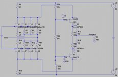
I build the attached circuit, input stage is biased with 6mA (IDSS 7.5), the FC-Fets are around 11mA, the most juicy I have.
I can't do distortion measurements, a square looks fine up to 70kHz, gain is plenty.
The working conditions for the FET's need refinement (wish I had some more V-grade parts)
PSU Voltage seems a bit low as well.
The input offset is around 4mV, which is a bit high for my liking, so no listening tests so far (I even havent a second riaa stage handy...)
Should be no problem to change it for non-inv input, however.
My reasoning was:
-Push-Pull enhances linearity
-No Diffamp helps noise
-Since MC-Carts are low on voltage and relativly juicy on current, Folded Cascode might present mostly it's sonic advantages here.
- haven't seen this topo for a phonopre here.
So, what do you think, is this a worthwhile approach?
Rüdiger
in the urge to build something useful with parts I already have in my bin, I sketched a phono input stage tonight.
I build the attached circuit, input stage is biased with 6mA (IDSS 7.5), the FC-Fets are around 11mA, the most juicy I have.
I can't do distortion measurements, a square looks fine up to 70kHz, gain is plenty.
The working conditions for the FET's need refinement (wish I had some more V-grade parts)
PSU Voltage seems a bit low as well.
The input offset is around 4mV, which is a bit high for my liking, so no listening tests so far (I even havent a second riaa stage handy...)
Should be no problem to change it for non-inv input, however.
My reasoning was:
-Push-Pull enhances linearity
-No Diffamp helps noise
-Since MC-Carts are low on voltage and relativly juicy on current, Folded Cascode might present mostly it's sonic advantages here.
- haven't seen this topo for a phonopre here.
So, what do you think, is this a worthwhile approach?
Rüdiger
Attachments
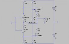
Won't R7 and R8 cause a loss of S/N since they're essentially in series between the cartridge and the FET inputs?
SY said:Won't R7 and R8 cause a loss of S/N since they're essentially in series between the cartridge and the FET inputs?
Hm, yes, that's true. I need them to bias the FET's, maybe I should look for lower IDSS in the first stage.
But then, 4mV Offset with Zout of 50R gives 0.08mA, which seems too high for a poor MC-Cart, doesn't it?
Rüdiger
I built the same topology with (medium) power transistors that are constructed with many parallel sections, good for low noise. I used a capacitor in the position of R5 in your figure. That capacitor made a huge difference in sound, depending on the type and value. Worth playing with it.
Onvinyl said:- haven't seen this topo for a phonopre here.
Rüdiger
If you apply the input to the gates it's pretty much identical to a Vendetta. And it solves the offset issue without having to match hundreds of fets.
As far as I know, the vendetta is differentialvendetta
And yes, if I can't make it run, I have to use the gates. Since I have good results in the phonnoclone with the inv. input, and the famous hiraga le prepre is using emitter input, I thought this might work better (at least with a middle to low impedance Cart with flat Frequency over impedance plot. Just wish there were such plots...)
Rüdiger
oshifis said:I built the same topology with (medium) power transistors that are constructed with many parallel sections, good for low noise. I used a capacitor in the position of R5 in your figure. That capacitor made a huge difference in sound, depending on the type and value. Worth playing with it.
Yes, I probably will parallel some FET's in the front end later.
Do you mean you *replace* R5 with a cap? I can't see how the thing could be working then?
Rüdiger
Onvinyl said:As far as I know, the vendetta is differential
Wrong.
Attachments
is there a way to vary the models of the FET's in LTSpice?
I get substantial differences in sim and reality looking at DC-operating points.
Rüdiger
I get substantial differences in sim and reality looking at DC-operating points.
Rüdiger
No, just bypass R5 with an electrolytic (plus perhaps some styro).Onvinyl said:Do you mean you *replace* R5 with a cap? I can't see how the thing could be working then?
Update.
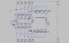
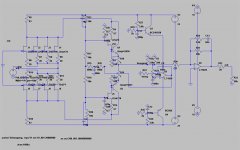
Here is a next try. Note that I don't have the shown mosfets in my bin so if I build it I have to use 610/9610.
The aim of the circuit was: good to great open loop specs, low noise, high slew rate and high bandwith to maintain the input stage test that is presented in us-pat.no. 4312060
Gain as shown is around 16dB, I wouldn't mind to get some more...
With the ideal voltage sources for the folded cascode fets the freq.-response is flat well past 100kHz, with resistive dividers (that I found often superior soundwise) the response drops substantially.
What can I use here? Jonathan Carr once said, he uses extra local regs for each and every cascode, I guess the main features should be good isolation from the rails, low noise and low output impedance. Do I have to use up my superreg-boards here ?
?
The output mosfest carry around 100mA, so the circuit might drive any possible riaa-network one can think of.
Do you think it's cool concept-wise or just ?
?
Rüdiger
Here is a next try. Note that I don't have the shown mosfets in my bin so if I build it I have to use 610/9610.
The aim of the circuit was: good to great open loop specs, low noise, high slew rate and high bandwith to maintain the input stage test that is presented in us-pat.no. 4312060
Gain as shown is around 16dB, I wouldn't mind to get some more...
With the ideal voltage sources for the folded cascode fets the freq.-response is flat well past 100kHz, with resistive dividers (that I found often superior soundwise) the response drops substantially.
What can I use here? Jonathan Carr once said, he uses extra local regs for each and every cascode, I guess the main features should be good isolation from the rails, low noise and low output impedance. Do I have to use up my superreg-boards here
?The output mosfest carry around 100mA, so the circuit might drive any possible riaa-network one can think of.
Do you think it's cool concept-wise or just
?Rüdiger
Attachments
Oops, a mistake.
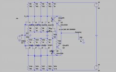
The drain resistors at the negative side have to be 332 R as well of course. The gain situation is much better with 30dB then.
Rüdiger
The drain resistors at the negative side have to be 332 R as well of course. The gain situation is much better with 30dB then.
Rüdiger
I've build the thing (actual values shown beneath).
With a 14R source, it has 30dB gain.
input fets sit at 7mA, cascode fet at 5mA and the mosfets carry 100mA,
not shown are the gate stoppers for the mosfets; here something can't be in order: I have to use 1k gate stoppers, with lower values, the ciruit oscillates.
Even though, it can only drive 4nF (parallel to the load) before it oscillates again (at a defined high freq).
This is not comfortable, since it shall drive the 2.12kHz pole of the riaa network, and I'll need to drive around 100nF.
I tried medium power bjt's instead, and while the -3dB point decreased from somewhere past 1Mhz to 700kHz (which shall be enough anyway), the bjt's drive any load without the faintest hint of oscillation (on a 50MHz-scope).
Any ideas what to try to make the mosfets stable?
I will make listening tests as soon as the second stage is up.
Other comments are welcome as well.
thanks,
Rüdiger
Attachments
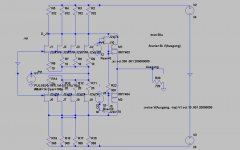
More refinements.
Since the output-bjt's work so effortless and stable, I decided to keep them (for now).
Shown here is a servo solution that I stll need to build. The second stage is indicative only. Opamps choice here is not what I would use in reality, just to keep the sim going.
The sim indicates a -3dB point at 4.5MHz without C39 (220n).
Every input FET is biased at 7mA, in reality I need 4.7R (not 20 resp. 30R as shown here), so I would need 56mA minimum in the folded cascode arrangement. With shown values we have some frightening 120mA.
I eventually would feed the gates of the input FET's instead of the sources, which would give me better sleep concerning offset, and maybe soundwise too.
Does someone know which parasitic C and L a Denon DL103-R has (and at what frequencies?)
Soundtest pending.
Rüdiger
EDIT: i will provide a cleaner drawing if this provokes some interest...
Attachments
- Status
- Not open for further replies.
- Home
- Source & Line
- Analogue Source
- MC Input Stage