So I have the opportunity to buy a UTC LS-65 output tx.
I've seen the regular utc schematics for this iron.
Was curious about using a McIntosh MC-60 circuit for them.
12AX7 > 12AU7 > 12BH7 > 12AX7 > 6550
amplificador Mcintosh MC-60
Is there any data for the three chokes used on the 6550's ???
One Plate choke per each output and the large cathode choke?
I'm assuming the Plate chokes are fairly small. And the cathode choke is probably a fairly high Henry choke.
Someone may even be selling these???
Thoughts / Ideas
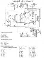
The MC-60 doesn't have chokes on the cathodes of the 6550's. The coils you see in the schematic are part of the output transformers.
The UTC's you have don't have those.
The UTC's you have don't have those.
Its quite an amplifier, that Macintosh. Gotta confess… didn't look at its schematic (tho' had the opportunity to) in the last few decades. Kind of a refreshing outlook on fairly simple amplification with a twist.
For instance (№ 1) — the first 12AX7 is drawn in a conventional (1960s, 1970s style) half-above and half-below implying LTP differential operation. Yet, it is not so, at all! The lower half of the 12AX7 is a voltage regulator, supplying about 120 volts apparently to the upper ½ anode as regulated B+. Cute, really cute.
Next (№ 2) — the combination of R10 and C5 is another 'power supply' to ensure the lower ½ of the 12AU7 gets a proper grid bias. Since the upper half is being driven without DC blocking capacitor from the prior stage, thus (again, presumably) at about +70 V grid. Nice.
Next (№ 3) — a bit of gain-reduction (and BTW negative feedback of sorts) with R16 = 330 kΩ. Not much, but still definitely some. 12BH7 pair of triodes continues to amplify differential signal, with fairly stout R17,20 anode loads. 12 kΩ. That's good for downwind stability.
Next (№ 4) — C9,10 DC blocking to allow the grids of the (surprise!) 12AX7 pair of cathode followers do their job. However, here's the surprise. Follow the BIAS back to C13, and in the notes you see a 1% capacitor! WTF! There's absolutely not a reason in the world for a 1% precision capacitor.
… which brings up the component values. Clearly someone well-after-copying-the-Macintosh-schematic annotated it with the cited values. Who knows how these 'selected' values relate to the original Macintosh ones. With the blunder above of specifying a 1% capacitor for a negative bias, and half-wave-rectified-at-that power supply leg, well … it puts the other components' values into question. At least for this old goat. ±20% for C13 would be just fine.
Next (№ 5) — that negative bias supply is HUGE, voltage wise. Something like what, –400 V? Clearly the Macintosh engineering team was “serendipitously” adding the negative supply from the mains transformer B+ secondary because they wouldn't need another winding. But –400 V is a big 'un. The combination of R22 and R19 voltage-divide it down to a more 'reasonable' 400 × ( 120 / (120 + 820) ) → –50 volts. … OK, that's covered. Gets the volts down to where the 6550's will want to see their grids biased at.
Next (№ 6) — however, it is kind of surprising that there is not bias-adjustment provisioning for the 6550's. Combo of R32 and R24 serve to raise the negative bias delivered by the 12AX7 cathodes to something around half that level.
_______
Bottom line, … no … the transformer you propose as noted by others, isn't the transformer for the job. Discussion of various chokes along the way, along with my suspicions of the component values, ought to lead you to research “the real deal”, and the original spec-values.
Just Saying,
GoatGuy ✓
Last edited:
Unity coupling. Duhhhh
I knew that. But damn if I didn't catch a case of the dumb....
Getting old is hell
I knew that. But damn if I didn't catch a case of the dumb....
Getting old is hell
With that kind of rectifier circuit the negative voltage depends on the value of C13, so the 1% isn't unreasonable at all.component values. Clearly someone well-after-copying-the-Macintosh-schematic annotated it with the cited values. Who knows how these 'selected' values relate to the original Macintosh ones. With the blunder above of specifying a 1% capacitor for a negative bias, and half-wave-rectified-at-that power supply leg, well … it puts the other components' values into question. At least for this old goat. ±20% for C13 would be just fine.
Mona
With that kind of rectifier circuit the negative voltage depends on the value of C13, so the 1% isn't unreasonable at all.
Mona
Mona, please explain with a bit of theory-detail for this Old Goat. I personally don't see how 9.8 µF is going to differ from 10.2 µF (2%) or 9.5 µF or 10.5 µF (5%) in the analysis of “with that kind of rectifier”. Seriously… I'm not trying to bait you, but I simply am not seeing the dependency. Thanks!!! GoatGuy ✓
You are right, it doesn'tMona, please explain with a bit of theory-detail for this Old Goat. I personally don't see how 9.8 µF is going to differ from 10.2 µF (2%) or 9.5 µF or 10.5 µF (5%)

I was thinking one could fine tune the voltage with that C as in front of a choke. But with a series resistors not so.
Mona
You are right, it doesn't
I was thinking one could fine tune the voltage with that C as in front of a choke. But with a series resistor not so. Mona
What a relief! … since I tend to take your comments as Sacred Gospel Itself, upon reading your initial critique, I became worried I might have missed something. Thank you again, Mona. —respect— back at you. GoatGuy ✓
- Home
- Amplifiers
- Tubes / Valves
- mc-60 utc