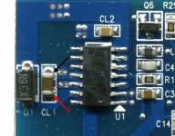
You should see a square wave with an amplitude of about 10v. The low side will drive to 10v above the negative rail. The high side will drive to about 10v above the source pad of the FET. You can ground the source pad of the FET to better view the gate waveform. Be absolutely sure that you don't have any solder bridges on the output transistor pads when grounding the source pad.
I didn't see any wave form on the pads. The 12,15 and 5v are percent on the driver board pins using the in individual grounds of the regulators.I will ground the source pad to see if it will show.Ground it using the secondary ground?
Original problem was shorted outputs.I replace the 1Ds 2Ds the two driver ICs and the 072 op-amp.
Original problem was shorted outputs.I replace the 1Ds 2Ds the two driver ICs and the 072 op-amp.
Are you sure that you don't have any solder bridges between the pads of any of the outputs?
Are you grounding the 3rd leg of the high-side outputs?
If there is no B+ supply across the high-side drive, you will need to supply one. It must be isolated. I use a 9v battery. Make sure you get the polarity correct.
Are you grounding the 3rd leg of the high-side outputs?
If there is no B+ supply across the high-side drive, you will need to supply one. It must be isolated. I use a 9v battery. Make sure you get the polarity correct.
- Status
- This old topic is closed. If you want to reopen this topic, contact a moderator using the "Report Post" button.
- Home
- General Interest
- Car Audio
- MB Quart 2000.1D
