well i was looking at some 17 cm woofers i still have laying around, and thought about using pcb material as stator, on thing possible with pcb (or at least more easy) is creating abnormal shapes.
so i thought of a sort of ring esl around my 17 cm woofer. the membrane is 3.5 cm wide, so dispersion should be pretty ok.
if i can trust sketchup i still end up wiht about
0.025545 m2 of surface. wich is as much as a 7 x 30 cm panel.
diameter of the panel is 18 cm and all the dots in the image ar drilled 3mm holes, i then remove coper around this hole to prevent arcing 4 or 5mm diameter. i then put the ring around the woofer. (this would have some consequences for the cassing of the woofer ofc)
Could this work? i remember that circular membranes where not the best, but in this case its not really a circle because the middle is not there.
i hope to be able to cross it around 2 or 3 k just like a normal 2 way design. maybe its even possible to lower that.
it also becomes a sort of point source although normally the tweeter is in the hart of the contraption 🙂
Attachments

Last edited:
oh i just thought of something , of it could be that if ur on axis (in the middle of the ring) you could have some over kill of off axis response because ur of axis of all the membrane, but if you play with the width of the ring it could counter the rising response of an esl. hmm much to think about because almost all theorie is based on rectangluar esl's with a ring there are so much more things that come into play
Dear WrineX
Look up the Quad ESL 63. This ESL is electrically segmented into circular and then concentric rings around it. These are then electrically delayed (or some would say filtered) but whatever the design successfully makes the ESL considerably less directional in the high frequencies and mid range compared to more conventional designs.
So since most will acknowledge that the Quad ESL 63 is a well built and designed electrostatic speaker, I would be surprised if anyone would suggest your "shape" is wrong or "stupid".
This said I would propose making the center electrostatic too and have less and less high frequencies going through your speaker the further from the center, Don't worry about the location of the Bass speaker so much, just keep it near the electrostatics, the lower you can cross over to the woofer the less critical the woofers location. I will possibly be building my first electrostatic speaker soon too.
Regards
Owen
If high frequency ring is made around the woofer then polar pattern will be difficult to predict with current modeling tools and will highly depend on listener angle. It is due to interference of sound waves emanating from different distances to the listener and crossing each other. Expect some pretty rough off axis response IMO.
Edit : you could test to get an idea by placing say two dynamic tweeters like 20cm apart, then measuring on and off axis response, both vertically and horizontally. I think it won't do very well. Actually similar effect is happening with stereo systems, but to far lower frequencies and is not difficult to observe.
Edit : you could test to get an idea by placing say two dynamic tweeters like 20cm apart, then measuring on and off axis response, both vertically and horizontally. I think it won't do very well. Actually similar effect is happening with stereo systems, but to far lower frequencies and is not difficult to observe.
Last edited:
Expect some pretty rough off axis response IMO.
I would also expect this, and should have made this point more clearly. Thanks for the clarification Bazukaz.
Regards
Owen
yeah, that could be a problem, but on the other hand if you have a line source like a large esl panel 1 meter long. you would have the same problem... high frequency's from the bottom part will arive later then the ones from the part wich is at the same height of your ears. same goes for the top part of the line ofcourse. ofcource the longer the line sourde the worse spread of high frequency vertical. that could help.
its still is a nice thing to test i think.
because of easter all shops are closed but ill try to get my hands on some pcb material tomorow , and might even give the cnc a shot at it. although the machine self needs some propper rebuild. i might make a prototype of this ring tomorow 🙂 maybe putting it on open bafle with the woofer for testing.not good for the low end but making a propper housing for the woofer is kind of painstaking because the ring needs to be openair. and the woofer does not. some weird box design i have to come up with.
Last edited:
yeah, that could be a problem, but on the other hand if you have a line source like a large esl panel 1 meter long. you would have the same problem... high frequency's from the bottom part will arive later then the ones from the part wich is at the same height of your ears.
The vertical dispersion of a straight vertical line source is very small and little interference pattern appears. That's ignoring reflections for sure.
Now when the same line source is bent into a circle you have a much different situation. There should be good circular pattern(no influence by rotation around the axis) but pretty bad results if the angle to source is changed. Thats my opinion.
Regards,
Lukas.
Last edited:
The vertical dispersion of a straight vertical line source is very small, therefore very little interference pattern appears when you move listener across it's height. That's ignoring reflections for sure.
Now when the same line source is bent into a circle you have a much different situation. There should be good circular pattern(no influence by rotation around the axis) but pretty bad results if the angle to source is changed. Thats my opinion.
Regards,
Lukas.
yeah the vertical dispersion i mentioned as wel indeed. only thing i dont know how bad it is in a line sourse because you cant measure it 🙂, probable less then my circle 🙂
yeah im almost sure its gone be some weird interference. im really lookjng forward of measuring such device 🙂
We can not measure a theorethical line source with infinite height and infinitely thin, but an approximation we can.
A near field measurement of a large narrow element would be more or less acceptable to get an idea what is happening.
I think we can discuss to death about theory which most of us(including me) cannot grasp completely, so some measurements are very valuable.
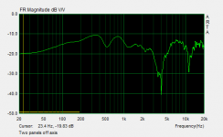
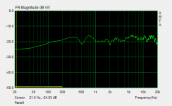
See screenshots of one and two ESL 150x30 cm, with treble segment(s) 2 cm wide.
1) Frequency response of two panels side by side, somewhat off axis
2) Frequency response of a single panel.
In picture 2) I can see no significant interference pattern in the SPL which is extremely obvious in 1).
A near field measurement of a large narrow element would be more or less acceptable to get an idea what is happening.
I think we can discuss to death about theory which most of us(including me) cannot grasp completely, so some measurements are very valuable.
See screenshots of one and two ESL 150x30 cm, with treble segment(s) 2 cm wide.
1) Frequency response of two panels side by side, somewhat off axis
2) Frequency response of a single panel.
In picture 2) I can see no significant interference pattern in the SPL which is extremely obvious in 1).
Attachments
Last edited:
If high frequency ring is made around the woofer then polar pattern will be difficult to predict with current modeling tools and will highly depend on listener angle. It is due to interference of sound waves emanating from different distances to the listener and crossing each other. Expect some pretty rough off axis response IMO.
.
Actually, the response is quite easy to calculate. It is the difference between two concentric diaphragms, one of 24cm diameter and the other of 17cm diameter. Since each would have horrible off axis response at high frequencies, I would expect the difference response to be equally bad.
Not worthwhile pursuing!
Andrew
Well THE esl is not 24 cm in diameter , it's a ring so actually it's 3 cm wide. Of axis should be ok at 3 cm, de woofer ofc will not have good of axis at high freq but it should crossed bellow 2 K or something. You are right that it could end up in complete failure. But it is hard to tell what it is going to do exactly
Well THE esl is not 24 cm in diameter , it's a ring so actually it's 3 cm wide. Of axis should be ok at 3 cm…But it is hard to tell what it is going to do exactly
Off axis response deteriorates because of path length difference between different areas of a radiator. The differing path lengths shift the phase of the sound arriving from different areas resulting in cancellation rather than summation. So even if your ring is 3cm wide, there will be a considerable path length difference between areas of the left and right sides of the ring when listening off axis. Note difference in red and green lines in Attachment #1.
As AndrewJ mentioned, the off-axis response for the ring will simply be that for a 24cm piston minus that for a 17cm piston. You can calculate this using the Bessel directivity function for a piston that can be found in any acoustics text, or brute force summation of a large number of point sources distributed around the 3cm ring. The results are the same, and are plotted in Attachment #2 for a couple off axis angles.
Note that the ring has worse off-axis response than even the 24cm piston.
Looking again at Attachment #1, you can see that this makes sense because when you remove the inner 17cm area from the 24cm piston there will now be(on average) larger differences in path length between all areas of the radiator.
Attachments

- Status
- Not open for further replies.
- Home
- Loudspeakers
- Planars & Exotics
- Maybe a stupid esl shape ?