Been pondering IIR crossovers some more...always dangerous for me, being the die hard linear-phase xover dude I am...lol
Many are no doubt familiar with Linkwitz's cascading strategy found at https://www.linkwitzlab.com/frontiers_5.htm#V
First from that link, it's shown how a parallel 4-channel topology has its issues, and that cascacading is a definite improvement.

Then next, the bold text in the snip below describes adding an all-pass to the SW (sub) channel based on the W channels low-pass frequency,
improves response further.

I think there is a better way, and not much harder to implement, ......particularly if you have an open-architecture processor than lets you place filters in series as needed.
Cascading high passes is retained....but the recommended SW all-pass gets dropped,
in exchange for putting all the low-passes used in higher channels, in series after a channel's principal low pass..
So for example, using the W channel which has a principal low pass at 200Hz. It gains a second low-pass in series at 2000Hz (The M channel principal low-pass).

With the above flow put into a processor, here's the measured T+M+W+SW summation.

So zero ripple.
With no level adjustments, delays, or all-pass, on any channels.
Maybe there's holes in this.....i dunno..
again, i'm NOT an IIR man 😛
I figure the ripple free results can most likely be achieved through the use of more all-pass filters in series on the channels, akin to the low pass strategy I used.
But I'm like why bother with that?
When the low-pass strategy is so straightforward and simple....
Folks who do know IIR... please correct any/all of this if I'm barking up a tree (again LOL) ...thx, mark
Many are no doubt familiar with Linkwitz's cascading strategy found at https://www.linkwitzlab.com/frontiers_5.htm#V
First from that link, it's shown how a parallel 4-channel topology has its issues, and that cascacading is a definite improvement.
Then next, the bold text in the snip below describes adding an all-pass to the SW (sub) channel based on the W channels low-pass frequency,
improves response further.
I think there is a better way, and not much harder to implement, ......particularly if you have an open-architecture processor than lets you place filters in series as needed.
Cascading high passes is retained....but the recommended SW all-pass gets dropped,
in exchange for putting all the low-passes used in higher channels, in series after a channel's principal low pass..
So for example, using the W channel which has a principal low pass at 200Hz. It gains a second low-pass in series at 2000Hz (The M channel principal low-pass).
With the above flow put into a processor, here's the measured T+M+W+SW summation.
So zero ripple.
With no level adjustments, delays, or all-pass, on any channels.
Maybe there's holes in this.....i dunno..
again, i'm NOT an IIR man 😛
I figure the ripple free results can most likely be achieved through the use of more all-pass filters in series on the channels, akin to the low pass strategy I used.
But I'm like why bother with that?
When the low-pass strategy is so straightforward and simple....
Folks who do know IIR... please correct any/all of this if I'm barking up a tree (again LOL) ...thx, mark
The sum is supposed to be perfectly flat with the all-pass(es) in place - in the continuous-time case anyway, when you make it discrete-time it may depend on how you transform it to discrete time.
Ahh, thx. Just measured real time, as per Linkwitz's page recommendation......yep, maximally flat, like what I was doing...The sum is supposed to be perfectly flat with the all-pass(es) in place - in the continuous-time case anyway, when you make it discrete-time it may depend on how you transform it to discrete time.
The final graph on his page made it look like ripple remained.
Honestly I always have had the opinion that SL's argument that the cascaded topology should be used was very specious. After all , we are not trying to direct certain audio bands into resistors, are we? That is all that he is showing, that for channels that have no further influence on the audio the sum is slightly "better" for the cascaded topology. OK, now let's assume you are actually designing a loudspeaker (since we are). Then there is the amplitude and phase responses of the acoustic output of each driver in the system to deal with, and these will (strongly) perturb the summation too. It's why you cannot just dial up some prefab crossover filters on a pro audio crossover box and get a good result. So, since we are going to be adding in a bunch of other filters that will compensate for the frequency and phase problems that real world drivers represent, why not fold into them the phase compensations that will make the crossover filters nicely sum together? Since we will be doing that, it really doesn't matter whether you use the parallel or cascaded topology. It's really a non-issue when you look at it from the perspective of loudspeaker crossover design.

Thanks Charlie,
I think you make good sense. There's just too much to juggle with relatively low order IIR, to think perfect electrical summations will mean that much to final acoustic summations..
I guess, and only because I've seen how we almost can treat xover design when fully taking in drivers' acoustic responses,
as "summing into resistors" when using steep linear phase xovers....
that I just keep toying out of curiosity, to see if I can find any IIR mousetrap at least somewhat close in capability..
I should know better by now...sigh..
Like Lars Risbo wrote on another thread, loudspeaker design has developped from trial and error to designs with a solid theoretical basis and back to trial and error, but now using simulators and optimizers instead of real trials. I think Siegfried Linkwitz was from the intermediate phase, so he would naturally prefer to start with something that is conceptually right and works perfectly under ideal conditions, then look at the effect of practical limitations, then find ways to make it work well within those limitations.
Low frequency IIR stages may be more prone to rounding errors and digital noise, at least if the software only uses 32 bit floats instead of doubles or something like that. Sometimes a small curveball like that, hidden in 3rd party soft/hardware, may disrupt great plans to deploy highly optimised filters like a stacked 50 Hz + 200 Hz + 2kHz hpf to the tweeter.
In a similar vein, straight out of uni, I jumped right into analogue active filters as the greatest thing ever. Eons later, I made the connection that the most dominant form of speaker in existence has stray inductance that is non-linear, and modulated every which way, by things like coil displacement and magnet memory. Leading to a rabbit hole of voltage vs current drive control techniques for power amplifiers.
In some cases, it could be beneficial to use ordinary air-cored chokes to control the impedance (raising it at high frequencies) between the ampifier and speaker to reduce distortion, and then clean up the FR actively. E.g. the mid could have a 6dB/oct roll off above 1kHz passively, only to be boosted actively with a high pass shelf to extend its range.
@MarclelvdG
That's an interesting historical view on how loudspeaker design has progressed...my thx to you and Lars for those thoughts.
I guess I find my approach akin to the intermediate era you describe of Siegfried Linkwitz.
I like to start with conceptually right, and then trial and error.
For trial and error, I don't like modeling so much.. How do know if model results are right or wrong? Unless I measure or hear them?
So I tend to measure concepts first, then model after they seem to hold water.
The whole design process really is interesting to contemplate...huh? 🙂
Hi OP, I'm curious about something I know very little about. I get the issue with the narrow filters on the woofer... but for the sub to woofer problem, is this not just something to fix with a delay setting instead of 2 additional filters??
Thank you,
Erik
Thank you,
Erik
Hi Greg, I've been 1000% positive i wasn't presenting anything new.An excerpt from the Merlin ISP-100 user's manual that I wrote back in 1995.
The only "newness" I guess, is how easy it is with open architecture DSP to replicate designs. And just do it.
From the attachment you gave, I assume the smaller unlabeled boxes, without info are just the extra needed hpf's and lpf's at the correct corresponding frequencies?
Hi Erik,Hi OP, I'm curious about something I know very little about. I get the issue with the narrow filters on the woofer... but for the sub to woofer problem, is this not just something to fix with a delay setting instead of 2 additional filters??
Thank you,
Erik
The choice of the narrow filters on the woofer was just what SL had used for his presentation.
Really had nothing to do with sub-to-woofer integration principles.
Fixed time delay, and phase rotational alignment.... cannot be substituted one for another.
It's an aah,ha moment when grasped.
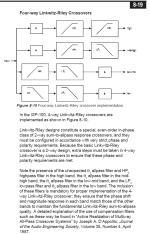
In the first vertical column, from top to bottom, are "phi1", "phi1", "HP1", and "LP1". They all cross-over at the same frequency; "phi1" is an allpass appropriate for the order of the LR filter pair composed of "HP1" and "LP1". This is the low to low-mid crossover.
In the second vertical column, from top to bottom, are "HP2", "HP2", "LP2", and "LP2". They all cross-over at the same frequency; they represent a LR filter pair. This is the low-mid to mid-high crossover.
In the third vertical column, from top to bottom, are "HP3", "LP3", "phi3", and "phi3". They all cross-over at the same frequency; "HP3" and "LP3" represent a LR filter pair, and "phi3" is an allpass filter appropriate for the order of that LR filter pair. This is the mid-high to high crossover.
It is best if you can look-up the cited paper by D'Appolito.
Fixed time delay, and phase rotational alignment.... cannot be substituted one for another.
Right, I guess I'm trying to understand the nature of the problem based on my knowledge of how linear phase LR 4 filters work.
So we're saying that normally an LR4 HP and LP filters would sum to zero, and any issues with acoustic distances ot the drivers can be solved by time delay. We're also saying htat in this particular case, because the woofer has such a small bandwidth, the woofer's LP filter is interfering with the HP so that fixed time delay no longer is a possible solution?
So, next question... is the HP filter no longer linear phase?? I mean, is the problem the shape of the HP filter... or has the phase alone been altered?
Linear phase LR 4 filters? Linkwitz-Riley filters as defined by Linkwitz are not linear phase. They are minimum phase, and when you add or subtract (depending on the order) the outputs of a Linkwitz-Riley low-pass and the corresponding Linkwitz-Riley high-pass, the result is an all-pass filter.
My mistakeLinear phase LR 4 filters? Linkwitz-Riley filters as defined by Linkwitz are not linear phase. They are minimum phase,
Thanks for the follow up info. 🙂It is best if you can look-up the cited paper by D'Appolito.
I'm going to move on and hopefully stop toying with IIR crossovers for good. Lol
What motivated this 4-way LR-24 post, was I had seen that for first order Butterworth how the strategy of cascaded high-passes with low-passes in series, gave a 4 or 5 way a good chance of working with only moderate EQ's needed to address pure electronic residual ripple.
So just out of curiosity, I tried it for LR 24's, saw it worked even better, and thought, hey some folks might like this.
The first order BW implementation though, was a very real experiment for me. I felt it was the only IIR implementation that might challenge the steep (96 dB/oct) linear-phase xovers I swear by. The Idea being maybe I could get both flat phase with IIR, and its zero pre-ring potential.
Since I have wide driver bandwidth overlaps on the syn/unity horn I'm working with, the first order xovers went in pretty easy other than a much greater need for out-of-band IIR EQs, to bring each driver to match a first order acoustic target.
Project was a big fail though.
I didn't like what I measured or heard. Polars were clearly worse than using steep lin-phase; and subjectively the whole speaker lost a lot of clarity.
Anyway, thought you might find the saga interesting...
Hi, yes, for a two way with just a single LR4 crossover, mag will sum to zero and both drivers will be in phase with each other....given no acoustic center offset.So we're saying that normally an LR4 HP and LP filters would sum to zero, and any issues with acoustic distances ot the drivers can be solved by time delay.
And yes again, any acoustic offset can be solved with fixed time delay ( to a particular point in measurement/listening space.
I don't think the woofer's small bandwidth matters. The issue is that we went beyond a single two-way crosssover, and then how the additional crossovers' phase rotations effect each other.We're also saying htat in this particular case, because the woofer has such a small bandwidth, the woofer's LP filter is interfering with the HP so that fixed time delay no longer is a possible solution?
Fixed time delay still does not enter the picture for the multi-ways...it's still just a function of acoustic center offsets.
Hope that made sense
I don't think the woofer's small bandwidth matters. The issue is that we went beyond a single two-way crosssover, and then how the additional crossovers' phase rotations effect each other.
Waaaaaaaaaait a moment!! 😀 Assuming all LR4 filters.
So if the woofer was crossed at say 100 Hz and 1 kHz, and then there were 3 other drivers above that... mid bass, mid, tweeter, you are saying that the 100 Hz HP filter cannot be ideally mated to the woofer (also at 100 Hz, LR4) using just delay, because the upstream filters exist?? Is this even possible with parallel filter design? Or is this something that's only an issue when cascading filters??
Last edited:
I'm not really following you?? Fixed delay doesn't fit in anywhere.
Hey, here's another Linkwitz paper that dives in better than the linked page in thread opener.
Just found it...it says to use cascading with all-passes on all channels SW, W, an M. (IOW, already doing the same thing I was showing.)
Mandatory prerequisite reading for parallel vs cascading (if you haven't already)
- Home
- Loudspeakers
- Multi-Way
- Maybe a better way to cascade Linkwitz-Riley filters...