Am I correct in thinking that the maximum length of the midrange port tubes for a multiple entry horn is constrained by the first open pipe mode? I.E. if I wanted a driver to operate up to 800Hz the entry tube must be less then 0.215 m long?
I had a go at adjusting the port tube length (Lp) in the Hornresp multiple entry horn wizard but it appeared to have no effect on the response even for very large values so I presume effects of this length are not modelled?
I had a go at adjusting the port tube length (Lp) in the Hornresp multiple entry horn wizard but it appeared to have no effect on the response even for very large values so I presume effects of this length are not modelled?
I had a go at adjusting the port tube length (Lp) in the Hornresp multiple entry horn wizard but it appeared to have no effect on the response even for very large values so I presume effects of this length are not modelled?
You presume wrong 🙂. The MEH model takes all input parameter values into account.
Attachments
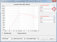
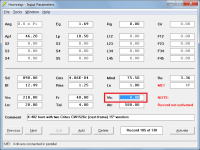
This is quite odd I'm not seeing any change in response with varying Lp. I'm trying to run the simulation here:
A K-402-Based Full-Range Multiple-Entry Horn - Page 4 - Technical/Modifications - The Klipsch Audio Community
there is a warning for this simulation that Atc is < Sd but I would expect this for a compression driver?
A K-402-Based Full-Range Multiple-Entry Horn - Page 4 - Technical/Modifications - The Klipsch Audio Community
there is a warning for this simulation that Atc is < Sd but I would expect this for a compression driver?
Attachments
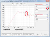
This is quite odd I'm not seeing any change in response with varying Lp.
That's because you have Vtc set to zero in the ME1 record 🙂.
Attachments
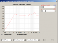
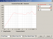
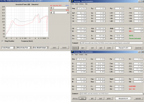
Many thanks for the great software and helping with this. I have made what I think are some fixes to the input parameters:
1) set Vtc to 4600 cm^3 (rough estimate of a 15" woofer cone volume)
2) set Lp to 2.8cm based on the horn wall been 1cm thick and 18mm MDF used as the mounting plate from the pictures
What then surprised me was a considerable loss in output in the bass range when I increased Lp. Something to do with loss of horn loading by the tube forming an acoustical impedance? or is this something basic like the woofer is acting like a poorly tuned 4th order bandpass?
I'm not sure if I care about the loss of efficiency as my goal with the long port tubes was more to do with reducing frontal cabinet area and good polar response rather than increasing efficiency. I was going to use a 100dB/W 15" driver and only aiming for response to ~80Hz.
Attachments
4 x 15" with only 12.5 BL motor in 218L 4th bandpass to feed the horn. If you want to go this road, you'll need 16-20BL motor. They'll be probably more inductive, but it should help too (use of semi-inductance model is really recommended). And try tweaking front chamber volume too. I've simulated this road, it seems possible. Or try to compensate weak motor using them in isobaric configuration instead.
4 x 15" with only 12.5 BL motor in 218L 4th bandpass to feed the horn. If you want to go this road, you'll need 16-20BL motor. They'll be probably more inductive, but it should help too (use of semi-inductance model is really recommended). And try tweaking front chamber volume too. I've simulated this road, it seems possible. Or try to compensate weak motor using them in isobaric configuration instead.
This sim is someone else's project I'm just trying to get the hang of simulation of multiple entry horns. I was planning on using a single 15", positioned behind a 2" compression driver. Hence why I needed to check if long ports were possible.
1) set Vtc to 4600 cm^3 (rough estimate of a 15" woofer cone volume)
The ME1 values of Vrc, Ap, Ap1, Vtc and Atc need to be the sum totals of the chamber volumes and areas for all the ME1 drivers, not just one.
The ME1 values of Vrc, Ap, Ap1, Vtc and Atc need to be the sum totals of the chamber volumes and areas for all the ME1 drivers, not just one.
So the hornwas put in this box (kpt-305):
http://www.specsserver.com/CACHE/FRLYREJHQGWY.PDF
I estimate the remaining volume to be 220L so the specified 218L seems accurate.
The driver specs are similar to those found here (for a single driver):
Specs for Crites CW1526C woofer? | Audiokarma Home Audio Stereo Discussion Forums
I also noticed that that there are 4 ports into the horn and 4 drivers simulated in hornresp but only 2 drivers on the actual horn. When I change the number of drivers in hornresp the response changes a lot. My point of confusion is that its not correct to simulate multiple drivers by increasing Nd?
There's dual ports/driver, so to get HR to calculate the correct pipe end correction, [4] drivers are required. When building it though, you need to quarter the volumes/areas [not port specs].
Increasing the number of drivers won't auto increase the various volumes, areas; these have to be inputted, so yeah, the response will go [really] wonky with increasing number of drivers crammed into a cab designed for just one.
GM
Increasing the number of drivers won't auto increase the various volumes, areas; these have to be inputted, so yeah, the response will go [really] wonky with increasing number of drivers crammed into a cab designed for just one.
GM
Last edited:
- Status
- Not open for further replies.
- Home
- Loudspeakers
- Multi-Way
- Maximum length of port tubes MEH/Synergy