Better so? Indicates far to much 3H at 5W. A2 indicates high power:"Mycket skrik för lite ull sa kärringen som rakade grisen" 😀

Last edited:
I will probably run my tubes on 51mA 3.5k 300V, something I decided before starting this thread. Seems this is better wrt odd overtones. Haven´t listened to it though. These are what I am working on. higher than 300V is probably useless, other then in AB PP´s.
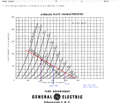
revintage - You need to take a look at the plate curves, draw your old-school load-line and see if that is what you want. My feeling is that it isn't really in a linear enough area. You can check my screenshot, a rough estimation based on a 3.5K load-line at your chosen bias point, assuming you have a decent enough driver which is swinging 60VAC P-P. See how the numbers on the bottom right corner are not the same? For some people (guitarists) this is no big deal... for us audio enthusiasts, it's a real source of distortion.
If you want to push the B+ then I would consider moving this load-like UP (like Tubelab does). Of course then you will be running your 6B4-G's beyond 15 Watts... When I get some time, I will try it (but only with some china 2a3's I happened to get for free).
Attachments

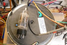
I have some that still test pretty close to 'new'.... Got them for free from a guy who wanted to replace them with 'new' because they were 'ugly'.Those good old reasonably priced chineese 2a3.ran them for 2-3 years and were reliable supprisingly. Did make the odd non audiofile noise occasionally.
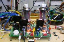
The pair in my post #8 picture are somewhere between 15 and 20 years old. They are 2 of the 6 that I bought, and all are still in good shape. The pair in the picture have been in the board since it was built. They got quite a bit of use when I lived in Florida with a 100 square foot workspace / listening room. 10 years ago I moved 1000 miles north and have a 2000 square foot basement for a workspace. 5 WPC doesn't quite cut it here, so the board with tubes sleeps on a shelf. Now I use some fat TV sweep (line output) tubes in UNSET, or should I say REDset. I get about 30 WPC from a pair of 6LW6's in near meltdown mode, about 20 in more normal conditions. I have tested 4 26HU5 tubes in parallel UNSET and I get about 40 WPC. The same pair of 26HU5's in an UNSET OUTPUT board driven in push pull by a Universal Driver board makes 200 watts at 3% THD on 600 volts before redness shows. If there are four tubes all sitting in UNSET Output boards, and a UD board to feed them, of course one must connect all 4 tubes to a "400 watt OPT and turn the knobs to the right. This yields over 350 watts at 0.817% THD with no global feedback applied. Turning the knobs a bit further nets 525 watts @ 3.79% THD. I gotta build me one of these!
Attachments

An ambitious design no doubt, I'sure it could sound good.Better so? Indicates far to much 3H at 5W. A2 indicates high power:
How about a single E/PC86 as input stage? Nice and linear with plenty of gain and low Zout, I bet they would get the job done even in a simple RC-coupled circuit. In fact, that's exactly how I did it in my old 6AV5GA amp, the IDH "equivalent" to 6B4G.
Thanks for the reminder. Don´t worry, I have done all loadslines and after that simmed. 3.5k, 300V ewill be good , especially if you want to keep H3 low. Please note, that in my latest sketch the driver is capable of more than +/- 100V.revintage - You need to take a look at the plate curves, draw your old-school load-line and see if that is what you want. My feeling is that it isn't really in a linear enough area. You can check my screenshot, a rough estimation based on a 3.5K load-line at your chosen bias point, assuming you have a decent enough driver which is swinging 60VAC P-P. See how the numbers on the bottom right corner are not the same? For some people (guitarists) this is no big deal... for us audio enthusiasts, it's a real source of distortion.
Thanks for your valuable input. No doubt it will work fine with EC86, problem is they relay on distortion cancellation. Anyway I also have a few EC86´s to try when my ideas fail.How about a single E/PC86 as input stage? Nice and linear with plenty of gain and low Zout, I bet they would get the job done even in a simple RC-coupled circuit. In fact, that's exactly how I did it in my old 6AV5GA amp, the IDH "equivalent" to 6B4G.
I run my 6B4G tubes at a little more than that, at around 350 volts. Both old the old Westinghouse and RCA tubes I've had at hand have held up brilliantly through the years. I use E83F as the driver, much transconductance gives enough gain and enough current to drive the grid capacitance of the output at the same time. Some distortion cancellation is applied, also 8dB of loop feedback.Want to use 6B4G as output tube in a SE amp with Ia 45mA. 2A3 is said to have Ua max 300V, but the specs for 6B4G says 325V with fixed bias AB at 40mA. Anyone who have tried 325V?
I still might have some PCB's left...
Attachments
- Home
- Amplifiers
- Tubes / Valves
- Max Ua on 6B4G