I've been enjoying the modified Parasound HCA-800 mkII. It's a simple lag-compensated amplifier, with a lead-lag network at the IPS to add some 2nd order loopgain roll off. No fancy modern TPC or TMC, just a classic topology that dates back to the JBL SA-600. It sounds live, with solid bass, it's a super detailed yet easy listener.
So what's the best we can do with lag compensation?
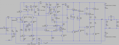
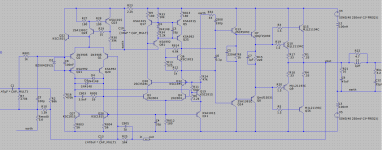
Here's an evolution of it with generous stability margins, and distortion products around -125dB, and that's with TO-3 outputs! Haven't built it yet but this might be the next project to be put to board.
So what's the best we can do with lag compensation?
Here's an evolution of it with generous stability margins, and distortion products around -125dB, and that's with TO-3 outputs! Haven't built it yet but this might be the next project to be put to board.
Attachments

More nice things about this circuit:
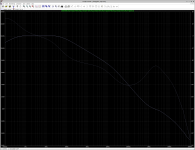
- There's no frequency response bump in the 250kHz range, like you often see with TPC amps. It just rolls off smoothly.
- Excellent PSRR even without active rail filtering. The IPS and VAS cascodes "soak up" rail AC voltages.
- The stability margins don't change much as the load varies from 2 ohms up to infinity. That's true for many amplifiers, but not all.

Hi, jpc2001. Please share the asc file to verify the scheme. Then, by joint efforts, we will be able to bring the scheme to working condition.
This can be tuned even better, with a heavier lag cap and a lighter lead-lag network.
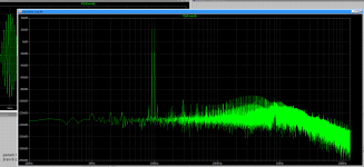
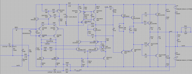
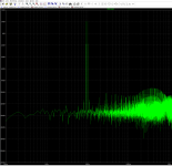
Switching to 3.9nF and 56 ohms at the IPS, and 330pF and 47 ohms* at the VAS yields better stability and distortion. Stability exceeds 70 degrees phase margin and 20dB gain margin. When playing a 9kHz + 10kHz test tone, the tricky 8kHz and 11kHz distortion products are now >130dB down. Dayuhm...
(*) OK so the VAS network is also a lead-lag network, that series resistor adds a little extra stability. Just don't use a value that's too large, we want the zero it creates to be near or above the dominant pole in the output transistors. The 330pF and 47 ohm values put the zero around 10MHz, which should be OK for these slow TO-3 outputs. For faster outputs, like 1302/3281 types, it should probably be >20MHz.
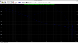
Alarmingly, substituting different transistor types at the IPS and VAS changes the stability margins on this amp. Swapping faster 2N3904/3906 transistors in at the IPS and VAS changes the loopgain plot to float up, raising ULGF to near 4MHz and reducing gain margin by half (see attached.) There's also an alarming loopgain spike around 57MHz; it might oscillate.
It's easy to fix this with some compensation changes, of course, but it's alarming that swapping transistors alone perturbs the stability so much. You'd rather it didn't...
I guess this happens because ULGF is a function of both the IPS and VAS transconductance, multiplied together. (Whereas in Miller compensated amps, and TPC/TMC too, only the IPS transconductance is a factor.) And that transconductance is a function of parasitics at higher frequencies. It didn't help that I started with slow (80MHz) KSA1015/1815 types which evidently contribute phase to the loopgain even in the 1-2MHz range.
I'm thinking we should spec fast types at the IPS and VAS, so that the variance in parasitics between individual transistors ought to be negligible. Then set the compensation for that.
Attachments
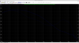
Here's the revised amp with faster IPS and VAS. Stability looks great: 75 degree phase margin, 19dB gain margin, with ULGF near 1.5MHz.
Distortion is still excellent, well below -120dB in-band.
The 57MHz loopgain peak is removed with the addition of a 33p cap to filter the feedback line from the VAS to the IPS current mirror. That is a feedback loop, and evidently needs its own compensation.
We don't appear to need fast transistors at the cascodes and mirrors. These structures aren't sensitive to small changes in transconductance. Below 10MHz, the cascodes are still cascoding, the mirrors are still mirroring, even using sub-100MHz transistors.
Attachments
@jpc2001:
thanks for posting your experiments on this; it was very interesting and useful reading!
not enough postings here on stability and compensation work.
PB2 is drumming up some good conversations in some other threads around here.
I'll point him to this one in case he hasn't seen it yet.
thanks for posting your experiments on this; it was very interesting and useful reading!
not enough postings here on stability and compensation work.
PB2 is drumming up some good conversations in some other threads around here.
I'll point him to this one in case he hasn't seen it yet.
this seems to align with comments from Tom Holman as he shared here some insights into the design of his still well-regarded APT 1 power amp from the late 1970s. He used 2N3904/2N3906 in VAS as bottom of cascode....
I'm thinking we should spec fast types at the IPS and VAS, so that the variance in parasitics between individual transistors ought to be negligible. Then set the compensation for that.
i'm curious if have you considered adding baker clamps to improve recovery time and mitigate the sticking?
I recommend emitter degeneration resistors at the input differential amp.
Otherwise hi-frequency roll-off of forward conductance will be an issue.
Otherwise hi-frequency roll-off of forward conductance will be an issue.
Hi mlloyd1, I looked a little bit at what options there could be for Baker clamps.
I found a clamp that keeps all transistors out of saturation, and yet the sticking looks no better. The problem is not saturation: the lead-lag network at the IPS charges up during clipping and needs time to discharge before the circuit returns to closed-loop operation again.
That seems like a weak point in this class of circuit, when compared to eg. Miller compensation or simple lag compensation. Not sure what the answer is yet. A feedback Baker clamp would probably work.
It's tempting to put an LED on the amplifier to indicate clipping, and rely on the user to notice and turn it down, and otherwise not worry about clipping...
Hi bucks bunny,
Emitter degeneration might have some advantages.
It might make the IPS and VAS transconductance a weaker function of transistor properties, and thus more reliable, so we might trust the simulated loopgain plot better.
IPS degeneration would allow shrinking the cap in the lead-lag network, and that should allow it recover from clipping faster (see my previous comment.)
I was getting better distortion numbers without degeneration, but it wouldn't hurt to lay out the PCB with spaces for those resistors just in case.
This is a good plan👍it wouldn't hurt to lay out the PCB with spaces for those resistors just in case.
KSC1845 KSA992 work great in the differential input. The new anp for sx3700 is using a dual differential input and VAS stage.
Whoa, I was wrong, we CAN add degeneration at the IPS and VAS without losing distortion performance or stability margin!
So this is very nice: it reduces LF loopgain. This allows a lighter lead-lag network, which provides faster slew rate and faster recovery from clipping. The degeneration also allows the circuit to tolerate imperfect current balance at either LTP better, with less loss of linearity.
So this is very nice: it reduces LF loopgain. This allows a lighter lead-lag network, which provides faster slew rate and faster recovery from clipping. The degeneration also allows the circuit to tolerate imperfect current balance at either LTP better, with less loss of linearity.
Attachments
We do not want a hi order phase lag summing up from all amplifying stages.
So it is advantageous to check 3dB corner for each stage individually within the simulation.
I learned a lot in doing so, for instance
-the 3dB corner of the differential amp was much lower than expected.
-the feedback resistor network together with input capacitance of diff amp forms another LP.
And so on, and so on...
- Home
- Amplifiers
- Solid State
- Max performance lag compensated amp