If the voltages are a bit low now, you might want to investigate why(low line voltage?). These voltages are off load, so they will drop further when you load the tranny up with connected tubes. Sometimes the voltages won't drop significantly, but keep an eye on it as you load it up. If the line voltage is low, or you just want to boost sec. voltage,you can compensate by wiring to the 110v pri. taps. They are normally used to seeing 110-or 220 for Europe? Then by putting a higher voltage 120- or 240 for Europe- It will give you a boost in your sec. voltage.
Last edited:
Thanks McGruff.
@boobtube: the voltage at the wall is 230, I think the transformer is expecting 240. If I wire to the 110 taps instead of the 120 I'd say Red would jump about 612 volts. Is this too high? Which is easier to deal with 560 or 612?
Is there any chance I could leave the brown & black taps connected (as it is currently) and simply move from the blue to the blue/yellow? Might this be a valid 230v configuration?
Last edited:
It might seem high, but it really depends on the voltage regulation of the transformer. I had one lying around and put it in an amp I built and the B+ dropped 50v from the off load voltage to full load. It just depends on the transformer and how much it is going to handle the connected load. The only way is to hook it up to the full load circuit and measure it.
Mcgruff has a good solution as well. Buy one of those plug in solid state replacements and try that also. You can always the re-wire the pri. if you don't get the results you need from that.
Mcgruff has a good solution as well. Buy one of those plug in solid state replacements and try that also. You can always the re-wire the pri. if you don't get the results you need from that.
I've just read 2 threads that suggest 230v wiring is possible. One thread on AX84 says they got this from Hammond:
"The primaries 110V and the 120V can be series connected to get 230V. It
is only parallel connections were the voltages must be the same to be
connected."
Is that the same as what I'm talking about?
"The primaries 110V and the 120V can be series connected to get 230V. It
is only parallel connections were the voltages must be the same to be
connected."
Is that the same as what I'm talking about?
Hmm even easier for me at this stage would be to connect brown to black/red.
So that would be:
- Live to 120V Blue
- 0V Brown connected to 110V Black/Red
- Neutral to 0V White
Or would my first suggestion be better:
- Live to 110V Blue/Yellow
- 0V Brown connected to 120V Black
- Neutral to 0v White
So that would be:
- Live to 120V Blue
- 0V Brown connected to 110V Black/Red
- Neutral to 0V White
Or would my first suggestion be better:
- Live to 110V Blue/Yellow
- 0V Brown connected to 120V Black
- Neutral to 0v White
Maybe the best action for now is to keep it hooked up the way you have it and see what your final B+ and other voltages will be. Maybe this transformer has better voltage regulation and your drop will be less than some other trannies. My experience has been voltage drops of 30-50 volts from off load to full load on the B+. You have a multi tap tranny, so leave all leads long enough to use all combinations if you want to change later. Mcgruff's solution is easiest for now. Just get the solid state adapter for the 5AR4 socket and see if the extra voltage from this is good enough if you are too low on B+. All I wanted you to be aware of is that off load voltage can sometimes drop by around 40 volts on full load and there is a solution to get that voltage raised by re-doing the primary. I don't think that SS adapter will give you that much extra but it might turn out that you don't need it. We really don't know which way to wire it until you have fired it up and measured all voltages on your initial voltage check out.
I guess I should have added you also need to consider those other voltages, 5v and 6.3v. If they also turn out to be low, then the only solution will be to boost voltages by re-wiring the primary.
I guess I should have added you also need to consider those other voltages, 5v and 6.3v. If they also turn out to be low, then the only solution will be to boost voltages by re-wiring the primary.
Last edited:
I've just read 2 threads that suggest 230v wiring is possible. One thread on AX84 says they got this from Hammond:
"The primaries 110V and the 120V can be series connected to get 230V. It
is only parallel connections were the voltages must be the same to be
connected."
Is that the same as what I'm talking about?
Yes, if you series connect a 120v and a 110v winding, this will match if you have 230v wall power. But you cannot parallel connect a 120v winding and a 110v winding. But you won't be paralleling them anyway because if you paralleled the 120v windings, this would match 120v wall power. Paralleled connections do not add voltagewise. The current(amperage) will double. Series connected windings will be additive voltagewise. If you series connect both 110v windings and put 230v on that then your secondary voltage will be higher according to the change in ratio. You are putting 230v on a 220v connected winding.
Personally, I'd be more concerned if the heater voltages were too high (vs. a bit low) since too-high heater (filament) voltages will shorten tube life quite a bit.I guess I should have added you also need to consider those other voltages, 5v and 6.3v. If they also turn out to be low, then the only solution will be to boost voltages by re-wiring the primary.
I've never been able to 'nail down' the B+ voltages until I get the amp working with all the tubes installed - it always seems to take some 'adjusting' of dropping resistors, and sometimes rectifier tube swapping, to get everything within spec. .
Of course, I'm usually dealing with a 'salvaged' PT from old gear, so the regulation is unknown to me.
So, I'd resist the temptation to look at the primary connections to solve a B+ problem, if the heater voltages are close to optimum.
Another issue is whether the line voltage varies much during the course of a day at the OP's location.
I've been told this 'improvising style of construction' would all change for me if I just did more computer simulations before I got the soldering iron heated up!😀
A little bit of progress. The primary side of the power transformer is wired in. It could have been a bit neater but I'm happy enough. It didn't blow up at least!
I tested the secondaries and they're a bit low, but hopefully ok?:
- red: 560
- green: 6.2
- red 4.8
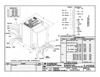
I believe on this transformer I should only wire the red/yellow to ground? Or should the green/yellow and yellow/black also go to the same ground?
http://www.hammondmfg.com/pdf/EDB370FX.pdf
But his off load voltage on both 5v and 6.3v are already a little low. They certainly won't go UP on full load. I don't think he has to worry about being too high as is wired right now.
And if you noticed, I already said for him to get voltage readings on initial check out and change only if all the voltages were too low at that time. See post #27.
I think your "improvising" style is the most fun. It's a way to learn more and see the result in what you changed. I like it best also.
Last edited:
I believe on this transformer I should only wire the red/yellow to ground? Or should the green/yellow and yellow/black also go to the same ground?
http://www.hammondmfg.com/pdf/EDB370FX.pdf
You've gotten good advice on this already:
The R/Y HV CT (center tap) needs to go to circuit ground if you are using a full-wave rectifier.
The 5v (rectifier heater) CT Y/Blk isn't normally used in the circuits I see.
The 6.3v (heater) CT G/Y connection depends on the ground scheme (if any) that you are using for your amp tube heaters. It can be connected to ground, or sometimes connected to a (moderate)+ DC voltage (from a voltage divider of some kind, usually) to 'lift' the heaters above ground.
One thing is certain: with the heater CT available there's no need for the 2x100ohm resistors tied across the heater circuit - to create an 'equivalent to a CT' that you often see in amp builds.
Thanks everyone, I'm getting an amazing education here!
I also subscribe to the learn-by-doing school of thought.
Just to clarify one thing further: does anyone have any thoughts on how I should proceed with changing the primary voltage i.e. is there any difference between changing which taps are currently linked vs changing the tap live currently goes to?
Hmm even easier for me at this stage would be to connect brown to black/red.
So that would be:
- Live to 120V Blue
- 0V Brown connected to 110V Black/Red
- Neutral to 0V White
Or would my first suggestion be better:
- Live to 110V Blue/Yellow
- 0V Brown connected to 120V Black
- Neutral to 0v White
Just to clarify one thing further: does anyone have any thoughts on how I should proceed with changing the primary voltage i.e. is there any difference between changing which taps are currently linked vs changing the tap live currently goes to?
As long as you connect together in series as the diagram from Hammond indicates ("top" to "bottom"), I don't think it makes much difference which of your choices above is used.
Either your 230v supply connected across 110+120 or 120+110,
OR to get higher voltages on all the secondaries:
Your 230v supply connected across 110+110 windings, OR
To get even higher voltages on the secondaries, connect your 230 v across combinations involving the 100 volt primary windings.
But as BT suggests, you won't find out for sure 'till you load up your transformer with tubes drawing (heater and B+) current.
Attachments
Last edited:
Thanks VictoriaGuy, I get that the voltages will drop under load alright.
I rewired it for 230 by connecting brown to black/red anyhow 🙂
Seems to be working fine. No load voltages are much healthier now:
Red = 595
Green = 6.6
Yellow = 5.1
If - when there's load - they drop significantly, I can always wire it for 220.
I rewired it for 230 by connecting brown to black/red anyhow 🙂
Seems to be working fine. No load voltages are much healthier now:
Red = 595
Green = 6.6
Yellow = 5.1
If - when there's load - they drop significantly, I can always wire it for 220.
Last edited:
Yes, you are good for now - I agree.Red = 595
Green = 6.6
Yellow = 5.1
If - when there's load - they drop significantly, I can always wire it for 220.
I'd rather run tubes at 6.0v heaters than at 6.6v, but the tubes will probably load down the transformer to the 'just right' heater voltages of 6.3v.


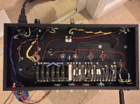
It lives!
I put in some epic soldering effort today to get it running. I'd miswired one of the rectifier heater wires (thankfully on an unused pin). But it was tracked down quickly, and once sorted it started amplifying. As far as I can tell it was my only mistake 🙂
It sounds fantastic. Chords are really solid and strong. It's very clean, maybe too clean: it only breaks up running flat out. Tone controls are excellent, bass and treble are super smooth and there's a wide sweet "area". It's not at all harsh or flabby. It is flipping loud!
There a tiny amount of hiss and hum: far less than my Fender Blues Junior, even at 3 times the volume - but perhaps more than I was expecting. I have some suspicions as to the sources.
I'm just running it through the blues junior standard speaker at the moment. But I'll get some samples tomorrow evening. I suspect it will sound even better with a greenback (that's the next job on the list!)
Thanks for everyone's help. I'm sure I'll have a million more questions once I start tinkering with it.
Some pictures attached.
Attachments

Just to be sure, you did do the initial voltage check? Sometimes higher plate voltage will give more headroom and cleaner signal. Remember about the possible voltage discrepancy from the off load voltages? They did go higher after the re-wire. Don't forget about the 6.3 and 5 volt readings as well and EL84 plate, screen and bias, preamp plate and bias.I think the lightning is supposed to break up sooner. Someone who knows for sure please correct me if I'm wrong. It should sound better through the Greenback and if it is new, even better after break-in. Super progress for your first build and it looks great, too!
Last edited:
Good work - and thanks for the pix. It's helpful to see a working low-noise layout. Look forward to hearing some clips.
Thanks guys.
Yea I did a quick check of the voltages last night and all seemed good so I cranked it up.
I rechecked them this morning:
EL84
- plate: 363
- screen: 246
- cathode: 9.1
I didn't have any reliable expected numbers... but plate seems a little high, screen and cathode a little low perhaps?
Should I be concerned??
- Status
- Not open for further replies.
- Home
- Live Sound
- Instruments and Amps
- Matchless Lightning inspired build