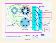
Wanting to make a fixture to match tubes on my Tek 575 Curve Tracer.
The curve tracer has connectors for the Emitter, Base, Collector up front. These are equivalent to:
Transistor--- Tube
Emitter-----Cathode
Base--------Grid
Collector----Plate (anode)
The curve tracer has connectors for the Emitter, Base, Collector up front. These are equivalent to:
Transistor--- Tube
Emitter-----Cathode
Base--------Grid
Collector----Plate (anode)
Wanting to make a fixture to match tubes on my Tek 575 Curve Tracer.
You'll also need a variable filament supply.
Rayma,
Understood, thank you.
Plan is to test mostly 12A*7 tubes, some 6L6 family tubes, and some 5U4G rectifiers. Supplying filament supply with a Variac, adjusting the AC Volts with a DMM. Grid voltage will be supplied with a DC power supply.
Some of the terminology varies. For example:
Filament= Heater
Plate = Anode
Grid = Screen
Plan is to test mostly 12A*7 tubes, some 6L6 family tubes, and some 5U4G rectifiers.
Supplying filament supply with a Variac, adjusting the AC Volts with a DMM. Grid voltage
will be supplied with a DC power supply.
This may be helpful, esp the part about jfets.
Tek 575 Curve Tracer
@Duke58 - You want to search for "glydeck" in the Yahoo TekScope user group, he made both triode and pentode test fixtures for the 575.
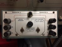
I've made tube fixtures for my 576 by stacking two 3x4 PCBs, drilling out the PCBs for banana plugs to match the 576 fixture and mounting two 9 pin sockets on the top layer PCB with a toggle switch to select triode A or B. Boards are held together with metal spacers and there is a screw facing down on the bottom layer to hit the safety interlock on the 576. Pretty easy to build, can be done in about an hour or less.
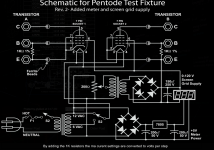
I've also built fixtures for 6L6/EL34/6550, which have a separate power input for screen grid. I use a bench top supply for the filaments.
I've also built fixtures for 6L6/EL34/6550, which have a separate power input for screen grid. I use a bench top supply for the filaments.
To match tubes, would I wire two of the same sockets with a switch between them to compare curve traces for each tube?
Like this:
For one thing, those are the incorrect sockets. I think you showed a sketch of the 9-pin miniature and the 8-pin octal.
From what I understand to properly trace the tubes you'll need to have the correct operating voltages. 6550s for an Ampeg SVT were talking +650V. That is fun. Do you have any GE6550s? or maybe some KT88s?
Don't take my word for it, but on the 6l6 types and other octals, isn't pin 8 to chassis ground, if I recall. At least in Fenders and through a 1 ohm or 10 ohm resistor can check the bias level indirectly.
The 10 ohm resistor gives you an extra digit on hand held meters.
Last edited:
- Status
- Not open for further replies.
- Home
- Design & Build
- Equipment & Tools
- Matching Tubes on a Tektronix 575 Curve Tracer Fixture