The set up: I have a couple of those cheap 6j1 preamps found on ebay that I bought for a project a couple of years ago. They work, provided way too much gain and made the bottom end of my system (pass labs amps, Theil speakers, Krell pre, etc) sound flabby, but worth keeping for a rainy day project. Moreover, using them will degrade the dynamics, or for that matter, any perceivable quality of my system. There are multiple schematics for this preamp and have not yet drawn the schematic based on the ones that I have. What I have seen deosn't show them drawn as true cathode followers, as I would have chosen for a buffer circuit. A couple of quick mods will fix that. For now, Let'sjust use the attach schematic.Fever 6j1 Tube Pre-amp Circuit - CircuitLab If this link doesn't work, let me know.I realize that well-designed differential outputs require a better starting point than this design. Let's just ignore that.
The Reason: I bought a dac with differential outputs that has enough gain that I can connect to the amp with a passive volume control. However, Its pretty bright. Rather than just selling it, as it does have some redeeming qualities, I thought I would put one of these preamps on the output of each channel, using the left and right channels to drive the inverted signals. I want to see what some harmonics and bandwidth limiting will do for the dac.
The problem: One of the most noticeable flaws of these units is the channel imbalance, making them bad options for driving differential signals. I haven't measured the output impedance to ground yet (which will be important to maximize cmr). The tubes certainly aren't matched and I would imagine that the transconductance of any 2 tubes will never match out of the box and always need some correction to maximize cmr. Although the 6j1 tubes are pentodes, they are implemented as triodes as far as I can tell.
The Question: To get matched differential voltage signals at the output of two different cathodes, am I just looking at rebiasing the tubes to make up for different transconductance values?
Am I correct in thinking that impedance at the output of a cathode follower depends on transconductance? If transconductance is a fixed characteristic of the tube design, can I ever adjust for matched impedance from signal to ground? Resistor network on the output?
Last edited:
I guess a little voltage imbalance is ok as I have heard that this creates the harmonics I am looking for. The different gain in each tube is significant, however. Even if I ignore this, I am concerned about the balanced impedance to ground.
Well the link shows a circuit that I would not use.
The cathodes are tied together, OK
One grid gets the signal.
The other grid is tied to one plate (max grid current burnout).
May just be a labeling problem, and that may be parallel plates.
But that does not show where the other grid is connected.
Also the circuit shows a volume control.
How well matched will your Dual volume control be? (you need Dual to take care of the + and - signals).
For stereo you need 2 matched Dual volume controls, or a Quad matched volume control.
Does you DAC have out of band signals?
Does it have too much distortion?
Distortion can be caused by passive volume controls that are to low of an impedance.
Is your passive volume control resistors, or transformers / auto-transformers?
Does your DAC need a better low pass filter.
These may be the cause of "bright" sound
We need to know many more details about your system.
I read your post and I can barely understand what you are trying to get across. I suspect you don't understand what the technical term "differential". As 6A3 says, you really have to give some details. What exactly is your DAC? What exactly is your preamp circuit? How exactly did you wire it up?
I'll rig up what I am thinking of tomorrow (and draw a pic) if you guys don't mind taking a look at then. Would be much appreciated. You might want to ignore this until then.
There isn't anything specific to the dac. It is a Digital Amplifier Company DAC1 tl. I have this issue with the Krell, anything played on SACD or most High rez audio, and even my Sunfire pre, which is pretty mellow (albeit somewhat muddy all-around). Its the worst when my wife talks. It's me. I have some hearing damage that causes sensitivity to high frequencies. I have wrong stereo set up for that as everything in my system is known to be a little unforgiving in the high end and was looking to see how I might bring down the highs a bit without an eq. The easiest solution might just be to pad down the tweeters, but I hate to disturb the Theil crossovers. I have a Monica Non-Oversampling dac in storage that I can listen to without issue. I can scrap all of this and go to that if need be and be ahead by a pretty penny to boot. But, I have these two preamps that did a fairly good job of limiting the top end of the spectrum while complimenting a nice midrange, which is a consequence of poor design. Thought I might try them essentially as tone controls.
I assume the volume pot is garbage like the rest of it. I will put a jumper across that to take it out of the equation. Lets assume no volume control needed.
I understand differential signals but sure I am asking the question in a way that makes little sense. This is in part becasue it is a poorly designed circuit to begin with and I am then using it in a way in which it wasn't intended. It will work, just not well wihtout some redesign. Differential signals should be inverted from each other, but equal in amplitude. They should also show the same impedance to ground to reject noise. There are other issues that they need to overcome as well, but lets not go beyond where we are.
I need two preamp modules to do this. One becomes the right line driver. The other becomes the Left. I want to use one preamp module (which has two drive channels, left and right) to drive a balanced signal. Lets say the right chanel of one preamp drives the signal on pin 2 and the left channel drives the signal on pin 3 on the xlr cable, with pin 1 to ground. Both are amplified, but because the transconductance is different on each channel, the amplitude is different. The tubes are not matched. To correctly match the amplitudes of the inverted signal from one tube to the other means that each tube needs to be biased with slightly different value resistors.
This will get the amplitudes to match, but how do I maintain impedance to ground. That is really what is required for noise rejection, not amplitude matching itself.
I read your post and I can barely understand what you are trying to get across. I suspect you don't understand what the technical term "differential". As 6A3 says, you really have to give some details. What exactly is your DAC? What exactly is your preamp circuit? How exactly did you wire it up?
I think the dac is irrelevant. This could be any piece of equipment with line-level balanced outputs. It isn't really about the source or amp. I'm not talking about impedance matching between components. I'm asking about matching the impedance between ground the voltage sources of pin 2 and 3.
this is an 6ak5 pentode wired as triode in a common cathode circuit working of voltage tripplers to supply +-28 volts off 12vac wall wart....
this is an effects box, not high fi, surely the price should be the dead giveaway, and if you can afford thousand dollar gear, why mess with this one?
this amp has been discussed here before...in another thread,
Ah, that clarifies things quite a bit, except that if that schematic is just "close" to what you, it is not worth any more words to discuss.
If things are as you say, that you are are using 2 of the stereo preamps just to amplify the balanced outputs of the DAC as 4 common cathode circuits, then you have 8 triodes doing very little, probably just adding noise. A differential circuit would be better, at least you would gain CMRR and the circuit would serve a real purpose.
If things are as you say, that you are are using 2 of the stereo preamps just to amplify the balanced outputs of the DAC as 4 common cathode circuits, then you have 8 triodes doing very little, probably just adding noise. A differential circuit would be better, at least you would gain CMRR and the circuit would serve a real purpose.
nothing much to see here folks, the chinese are known for their novelties, some are good but many are not so good, this type of amps have been discussed here and issues have fixes contributed by members....6J1 China preamp thoughts
Ah, that clarifies things quite a bit, except that if that schematic is just "close" to what you, it is not worth any more words to discuss.
If things are as you say, that you are are using 2 of the stereo preamps just to amplify the balanced outputs of the DAC as 4 common cathode circuits, then you have 8 triodes doing very little, probably just adding noise. A differential circuit would be better, at least you would gain CMRR and the circuit would serve a real purpose.
obviously a wrong application for this amp, unless he has an XLR so single ended phono plug cable...
I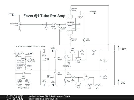
this is an 6ak5 pentode wired as triode in a common cathode circuit working of voltage tripplers to supply +-28 volts off 12vac wall wart....
this is an effects box, not high fi, surely the price should be the dead giveaway, and if you can afford thousand dollar gear, why mess with this one?
this amp has been discussed here before...in another thread,
Why ask Why? Its a dyi audio site. People like to experiment. 🙂 I should just buy a 1970 Pioneer sx440 like my father had when I was a kid and be done with it. That was the last thing I remember listeng to that didn't cause ear pain.
It has been discussed in many threads. But I am not using it in the manner that it was intended and not looking to redesign the circuit beyond matching the output impedance, which isn't an issue when you are driving single ended signals.
I'll draw it out tomorrow.
well, this is diyaudio, and you have every right to experiment....... 😀
just do not get yourself electrocuted...
you can in fact use two of these to make a fully balanced preamp.....this is doable...
if you can imagine it, you can do it....
just do not get yourself electrocuted...
you can in fact use two of these to make a fully balanced preamp.....this is doable...
if you can imagine it, you can do it....
Perhaps you can get some inspiration here?
The triode curves suggest to me that a CCS in each cathode would be the way to go. Or if you want to go to something more dependable (for matching) you could parallel the heater windings to one socket and use a low voltage double triode. (Assuming of course you want to use the two preamps you have because of the power supplies they contain.)
The triode curves suggest to me that a CCS in each cathode would be the way to go. Or if you want to go to something more dependable (for matching) you could parallel the heater windings to one socket and use a low voltage double triode. (Assuming of course you want to use the two preamps you have because of the power supplies they contain.)
Ahem, . . .
Something is wrong with the linked schematic in post #1.
Please take a look.
1. The schematic connects one grid directly to one plate.
2. The schematic also ties the two cathodes directly together.
You can do #1, Or you can do #2, but You can not do Both # 1 and # 2 at the same time.
(Not if you want it to work).
Last edited:
6ak5 pentode wired as a triode, there is nothing more to this....
and if the OP uses of these to make a balanced line amp, he can very well do that..
he will need four of these to make a stereo balanced line amp....
these are dirt cheap, nothing to lose sleep about...he can just go ahead and do it..
the fact that low B+ were used, tells of low output impedance...
and if the OP uses of these to make a balanced line amp, he can very well do that..
he will need four of these to make a stereo balanced line amp....
these are dirt cheap, nothing to lose sleep about...he can just go ahead and do it..
the fact that low B+ were used, tells of low output impedance...
OK, I see it now, there are 2 cathode pins but 1 cathode, g3 tied to cathode internally, g2 tied to anode externally.
I suggest you turn down treble a bit if you feel that sound overly treble-rich.The set up: I have a couple of those cheap 6j1 preamps found on ebay that I bought for a project a couple of years ago. They work, provided way too much gain and made the bottom end of my system (pass labs amps, Theil speakers, Krell pre, etc) sound flabby, but worth keeping for a rainy day project. Moreover, using them will degrade the dynamics, or for that matter, any perceivable quality of my system. There are multiple schematics for this preamp and have not yet drawn the schematic based on the ones that I have. What I have seen deosn't show them drawn as true cathode followers, as I would have chosen for a buffer circuit. A couple of quick mods will fix that. For now, Let'sjust use the attach schematic.Fever 6j1 Tube Pre-amp Circuit - CircuitLab If this link doesn't work, let me know.I realize that well-designed differential outputs require a better starting point than this design. Let's just ignore that.
The Reason: I bought a dac with differential outputs that has enough gain that I can connect to the amp with a passive volume control. However, Its pretty bright. Rather than just selling it, as it does have some redeeming qualities, I thought I would put one of these preamps on the output of each channel, using the left and right channels to drive the inverted signals. I want to see what some harmonics and bandwidth limiting will do for the dac.
The problem: One of the most noticeable flaws of these units is the channel imbalance, making them bad options for driving differential signals. I haven't measured the output impedance to ground yet (which will be important to maximize cmr). The tubes certainly aren't matched and I would imagine that the transconductance of any 2 tubes will never match out of the box and always need some correction to maximize cmr. Although the 6j1 tubes are pentodes, they are implemented as triodes as far as I can tell.
The Question: To get matched differential voltage signals at the output of two different cathodes, am I just looking at rebiasing the tubes to make up for different transconductance values?
Am I correct in thinking that impedance at the output of a cathode follower depends on transconductance? If transconductance is a fixed characteristic of the tube design, can I ever adjust for matched impedance from signal to ground? Resistor network on the output?
Involving a cheap ampstage won't solve anything only increase distortion.
Am I correct in thinking that impedance at the output of a cathode follower depends on transconductance? If transconductance is a fixed characteristic of the tube design, can I ever adjust for matched impedance from signal to ground? Resistor network on the output?
yes, for cathode follower gm is figure of merit...the higher your cathode current, the higher the gm and the lower the output impedance, 1/gm,
but here we have a common cathode circuit, where output impedance is more related to plate resistance and being low plate voltage, plate resistance is also low...
depending on the output impedance of the stage you are driving, which i suspect is greater than 10k ohms, then yous should have no problem...
I made several wrong assumptions at the start; and also as the thread continued.
I made a lot of mistakes that way.
Sorry for my misleading comments.
The Title, "Matching Triodes for Differential Outputs" confused me.
Using a pair of preamps each with a 5654 wired as a triode, does not have much chance of being balanced.
Instead,
Start with a double triode tube, couple the cathodes, use a CCS from the cathodes to ground (in this case a Constant Current Sink, not a Source), and use exactly matched plate loads. That has intrinsically matched gain.
Can not get much simpler, nor much more ideal than that.
That is a Differential amp, but the intrinsically matched gain will give equal amplitude outputs (if the DAC has equal amplitudes in the first place).
Build from scratch, rather than expending lots of energy to highly modify a couple of preamps that were not made for the original poster's application.
Now if the desire was to simply add 2nd harmonic distortion, that is easy . . . just mismatch the differential amp plate loads. Dial it in to the desired level of that effect.
- Home
- Amplifiers
- Tubes / Valves
- matching triodes for differential outputs