hello everybody.
I want to build a crossover from elliot sound products
(project 153 'Isolator' Equaliser)
and i need to match a power supply to provide +-15VDC i can’t choose if i should go for the p05-mini
(Project 05-Mini P05-Mini)
or the project 05 revision d
(Power Supply for Preamps)
the revision d has a optional muting relay circuit and first doesn’t have it.
overall they look similar to me (that’s why i can’t choose) but someone maybe has some experience with them or can give me some hints.
i want to build the crossover using the NE5532, they have max voltage +-22v but since i know, i can power the circuit using even simply -+ 12v isn’t?
thanks a lot for any help
Last edited:
The first one uses 78xx regulators.
The other uses LM31X regulators in which You can adjust Voltage if I'm not wrong.
I've built the second one and it worked fine.
If You don't need the relay, just leave the parts off.
The other uses LM31X regulators in which You can adjust Voltage if I'm not wrong.
I've built the second one and it worked fine.
If You don't need the relay, just leave the parts off.
no way, what's that piece of magic?😱
getting 230VAC and giving +-15 VDC? had no idea about it and i will check it!
any cons about using this instead of a regular AC/AC + project05? because it looks too attractive!
getting 230VAC and giving +-15 VDC? had no idea about it and i will check it!
any cons about using this instead of a regular AC/AC + project05? because it looks too attractive!
I use them in my project to power both a raspberry pi and a dac that I built, although it's the 5v version instead of the 15 15. Excellent results. Filter it to your desires if you want, simply. There may be smaller ones for you if you poke around the site, and yes, 12bucks, small, long life, wide supply V, and very easy to use. I use them exclusively and will not look back.
ok the here an another question. do they produce a lot of heat? ( i will put it inside od a 122mm x 66mm x 39.5mm box)
other question. where are you going to connect your mains ground? the smps has L/N input but no connection for ground.
other question. where are you going to connect your mains ground? the smps has L/N input but no connection for ground.
For a linear supply:ok the here an another question. do they produce a lot of heat? ( i will put it inside od a 122mm x 66mm x 39.5mm box)
Pd = (V_in - V_reg) / I_out
The xfmr should be no more than 12V + 12V out. That has losses, too - often around 1 W. I've seen tiny transformers (<3 VA, especially 1 VA and below) spec'd with idle losses exceeding their VA rating - bizarre. Would be nice to know who makes small and still efficient xfmrs. They are often run near saturation to keep primary winding resistance down, which makes voltage output stiffer under load. Eddy currents aren't necessarily minimized as well as humanly possible either. All a matter of cost.
These SMPS modules indicate about 70% efficiency at 2% of their nominal 20 W power output. So idle losses may be on the order of 0.2 W, not terribly much really, especially when compared to the linear version. (BTW - a measly crossover probably wouldn't need a module half as powerful, but hey, whatever works.)
The SMPS module itself does not need it, and you don't want to make a device handling unbalanced audio a Class I either.other question. where are you going to connect your mains ground? the smps has L/N input but no connection for ground.
Going by the datasheet, it appears that you would have to supply your own EMI suppression capacitor, connecting from secondary-side ground (Com) to PE. Must be a Y2 safety type, typically 4.7 nF or so. PE can also be used for other additional mains filtering if needed (a common-mode choke would be nice to have at least), but otherwise I would restrict its use to the primary side only. Everything primary side should be up to Class II (double insulated) standard, with appropriate spacing, gaps and insulation.
(It is not strictly required to treat PE is gingerly as this, however this approach would protect you even in case of a badly miswired outlet.)
The SMPS creates no more heat than a wal-wart.
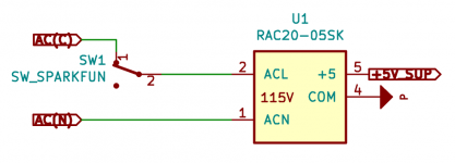
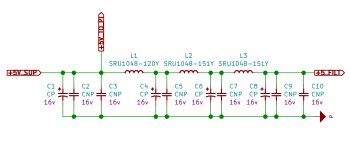
SMPS offer some advantages over traditional transformer based solutions in size and simplicity. One of the fears in SMPS is EMF and noise in the output, but you can go a great distance in this by simple filtering. Using an EMF meter, I have to put the meter nearly onto the SMPS to get it to pick it up, whereas it will pick up my phone EMF from across the room. In my project, since I use the Raspberry Pi, the Pi has it's own issues with making noise that for the most part, a linear supply wouldn't offer any advantages in the first place. Nearly any computer is going to make some EMF and noise on it's own. I have zero issues with my system even having the SMPS within 2.5" of the DAC. The Raspberry Pi is actually shielded on the back of a PCB in relation to the audio side of things.. So use your engineering skills to place components appropriately and I can say that you should have great results. In the attachments, one is just the simple AC connection, and the next shows how I filter slightly with a few capacitors for the Pi, and then chokes for the output before the audio circuits. Some parts are not labeled because I plan to use a variety of values. It's not necessary to go the the depth of filtering, but it's only a few dollars for me and the board space would be wasted anyway. Rod Elliot has a great page on grounding that you should take a look at..
Earthing (Grounding) Your Hi-Fi - Tricks and Techniques


My go-to EMF detector tends to be a portable AM/FM/shortwave radio, not the least because I happen to own a whole zoo. Shortwave on the whip antenna will tell you something about common-mode E fields, MW/LW on the ferrite rod will betray circulating currents.
Some of the cheapie stock wall-warts on my networking equipment were audible up to several meters. The difference to a linear power supply was particularly drastic on a TPLink WiFi router that became so quiet I could basically put the receiver right next to it. I haven't had quite the same luck with my current modem-router, I'm guessing the integrated VDSL modem is the problem and/or its board layout could be better.
Some of the cheapie stock wall-warts on my networking equipment were audible up to several meters. The difference to a linear power supply was particularly drastic on a TPLink WiFi router that became so quiet I could basically put the receiver right next to it. I haven't had quite the same luck with my current modem-router, I'm guessing the integrated VDSL modem is the problem and/or its board layout could be better.
- Home
- Amplifiers
- Power Supplies
- matching power supply +-15VDC for Elliot sound product Crossover