I am planning a power amp with two pairs of IRFP240/9240 driven by a LME49830. Do the MOSFETs absolutely need to be Vgs matched? If yes in which way: all four or just by N-ch/P-ch pairs? Thanks.
Jacques
Jacques
Hi,
typically matching of the paralleled mosfets (that would be N-N and P-P) is done to ensure equal turn on. For current sharing source degeneration is used.
N-P matching is rarely done and improves only even harmonic distortion cancellation a bit. However, the IRFP240 and IRFP9240 are much too different to benefit from that signficantly, so I would stick with N-N and P-P.
EDIT: I don't know your LME part, but does it include thermal compensation of the output stage? Otherwise you would need a vbe-multiplier or so to avoid thermal runaway of the output fets.
Last edited:
N-P matching is rarely done and improves only even harmonic distortion cancellation a bit. However, the IRFP240 and IRFP9240 are much too different to benefit from that signficantly, so I would stick with N-N and P-P.
EDIT: I don't know your LME part, but does it include thermal compensation of the output stage? Otherwise you would need a vbe-multiplier or so to avoid thermal runaway of the output fets.
Thanks for the tip H_a. Are you still selling matched pairs?
And yes, a vbe multiplier (BD139 sharing the MOSFET heatsink) is there as well.
Huh? The tempco of a V-MOSFET is the other way. They don't go into thermal runaway to the best of my understanding. That is one of their big advantages. Many designs just use resistors for the bias spreader because of this.
Huh? The tempco of a V-MOSFET is the other way. They don't go into thermal runaway to the best of my understanding. That is one of their big advantages. Many designs just use resistors for the bias spreader because of this.
I am not an expert but I always thought that vertical MOSFETs such as these IRPFs had a positive temperature coefficient (conduct more with temp) whereas lateral MOSFETs have a negative coefficient. Laterals usually don't require thermal compensation whereas verticals do. Please correct me if I am wrong.
Just read a datasheet, Vgs-Id graph.
Temperature goes, Id goes up for a vertical MOSFET up till 5-10 amps drain current : +/+ means positive.
Laterals have a positive tempco up to 50-100mA, negative temperature coefficient from there up.
Temperature goes, Id goes up for a vertical MOSFET up till 5-10 amps drain current : +/+ means positive.
Laterals have a positive tempco up to 50-100mA, negative temperature coefficient from there up.
You are correct. Mosfets like hexfets or plainer stripe fets require thermal compensation to operate with class AB bias. The N-type and P-type have different Gm figures. Nothing can be done about that aside from transistor choice but matching the like type pairs and appropriately sized source ballast resistors will help with current sharing.
a pair of irfp9140/240 make a better complementary pair, IF the supply rails are less than +-50Vdc.
for >+-50Vdc you have to use the 9240 for the p.
The parallel Ns must be matched for Vgs at their operating bias current.
Similarly the parallel Ps must be matched.
It would be nice to match at the operational Vds and operation temperature. This needs a lot of resources not generally available to us amateurs.
The Vfets MUST have a temperature compensating bias voltage. Very similar to BJTs.
Lateral mosFETs are the only device I know of that have a negative tempco at normal quiescent currents. i.e >100mA of output bias per pair.
The Source resistor does help in reducing the out of balance current. It does NOT eliminate it !!!!!!!!!! A higher value Source resistor also reduces the out of balance current.
Parallel outputs have in effect paralleled Source resistors. You can use a higher value Source resistor in parallel arrangements without reducing audio performance. Instead of 0r15 for a single pair, you could try 0r22 for 2pr and 0r33 for 3pr.
Hi AndrewT,a pair of irfp9140/240 make a better complementary pair, IF the supply rails are less than +-50Vdc.
for >+-50Vdc you have to use the 9240 for the p.
The parallel Ns must be matched for Vgs at their operating bias current.
Similarly the parallel Ps must be matched.
It would be nice to match at the operational Vds and operation temperature. This needs a lot of resources not generally available to us amateurs.
The Vfets MUST have a temperature compensating bias voltage. Very similar to BJTs.
Lateral mosFETs are the only device I know of that have a negative tempco at normal quiescent currents. i.e >100mA of output bias per pair.
The Source resistor does help in reducing the out of balance current. It does NOT eliminate it !!!!!!!!!! A higher value Source resistor also reduces the out of balance current.
Parallel outputs have in effect paralleled Source resistors. You can use a higher value Source resistor in parallel arrangements without reducing audio performance. Instead of 0r15 for a single pair, you could try 0r22 for 2pr and 0r33 for 3pr.
But why we still use IRFP240-9240 in class A amplifier such as F5 or
F5 turbo with parallel outputs...
can we use 9140 instead?
or better not changed because it is class A😕
Regards
ClassA generally run at lower rail voltages.
9140/240 would make an excellent pair for F5, F5t etc.
9140/240 would make an excellent pair for F5, F5t etc.
ClassA generally run at lower rail voltages.
9140/240 would make an excellent pair for F5, F5t etc.
Ok, thanks
but I already bought 240-9240 matched pair(n-n & p-p)
I have 9140 but not matched & it is very good for single pair output.
Will try that some time 🙂
ClassA generally run at lower rail voltages.
9140/240 would make an excellent pair for F5, F5t etc.
Hi Andrew, I've always hear that 9140/240 pair is better matched than 9240/240, even the spec sheet enforce the idea. However, BenY's measurement doesn't seem to say so.
However, current sharing between 9140/240 seems to be better match.
Do you think it's still better to use 9140 with the 240?
Ref. to thread of Beny's measurement: http://www.diyaudio.com/forums/solid-state/237219-fet-hex-explendit-amplifier-56.html
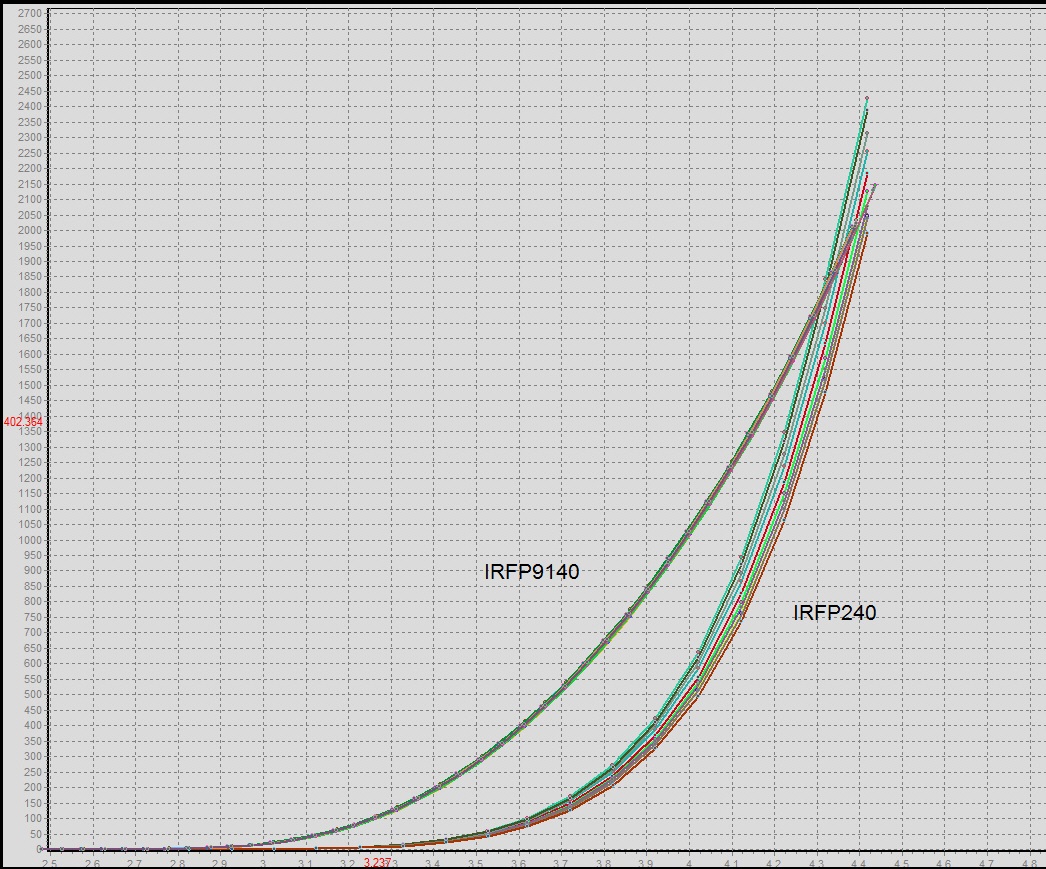
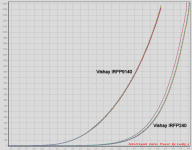
The top graph shows very different curves for the 9140 and 240
But what are the axes?
The different slope may be showing a gm difference
I don't know what the lower two graphs are comparing, is the last labeled correctly?
But what are the axes?
The different slope may be showing a gm difference
I don't know what the lower two graphs are comparing, is the last labeled correctly?
Hi Andrew, I do not know what measurements those graphs are for. However, I've PM BenY to see if he can elaborate on the data. Thanks.
Hi,
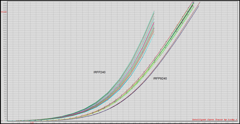
The vertical axis is the ID current and the Horizontal is for VGS..
Sorry for not pointing it out.
The vertical axis is the ID current and the Horizontal is for VGS..
Sorry for not pointing it out.
Back to the plots of real devices.
The middle plot shows irfp240 and irfp9240.
Both scales are linear.
Looking the Id range around 2A, we can see that the transconductance (slope) is higher for the irfp240. This is what the datasheet would state.
The top plot comparing irfp9140 to irfp240.
Looking again at Id of 2A
This time the transconductance of the irfp9140 is less than the irfp240.
This is different from the datasheet.
Any ideas why?
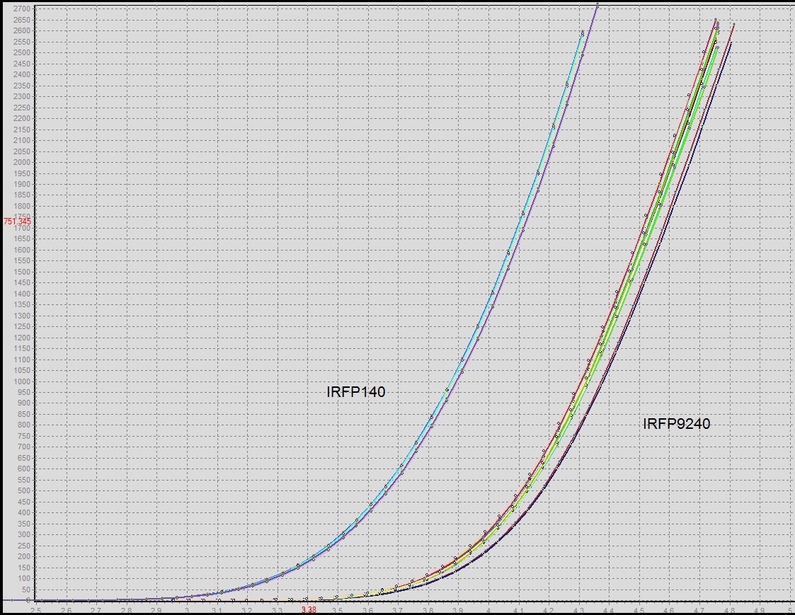
Finally looking at the bottom plots.
Could the device labels be wrong?
The middle plot shows irfp240 and irfp9240.
Both scales are linear.
Looking the Id range around 2A, we can see that the transconductance (slope) is higher for the irfp240. This is what the datasheet would state.
The top plot comparing irfp9140 to irfp240.
Looking again at Id of 2A
This time the transconductance of the irfp9140 is less than the irfp240.
This is different from the datasheet.
Any ideas why?
Finally looking at the bottom plots.
Could the device labels be wrong?
Back to the plots of real devices.
The top plot comparing irfp9140 to irfp240.
Looking again at Id of 2A
This time the transconductance of the irfp9140 is less than the irfp240.
This is different from the datasheet.
Any ideas why?
I have no idea why.
But data sheets are just a starting point, it gives you a range of min. and max. and what you actually get is somewhere in between, depending on the batch.
EDIT: Both the irfp9140 and the irfp140 are lower transconductance devices when compeared to the irfp240 & irfp9240. according to my curve tracer.
Back to the plots of real devices.
Finally looking at the bottom plots.
Could the device labels be wrong?
I bought these devices from mouser not too long ago,These are Vishay devices. Beyond that i have no control on the lables. But i mesured and marked them correctly.
Last edited:
Not the device marking..............I bought these devices from mouser not too long ago,These are Vishay devices. Beyond that i have no control on the lables. But i mesured and marked them correctly.
The labels on the plot seem wrong to me, i.e. I can't explain what I see.
Not the device marking.
The labels on the plot seem wrong to me, i.e. I can't explain what I see.
The labels on the last plot are correct.
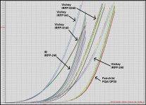
But, I would like to bring in new information i gathered.
First, The IRFP-240 devices i was measuring were an old "International Rectifier" devices,Purchased from Digikey around 15 years ago.
Lately i acquired new samples of Vishay IRFP-240 from Mouser, and they are somewhat different devices..
So i present all the plots on one window,including the manufacturer name and part number, to make it much clearer this time around.
You can clearly see that device parameters can change form one manufacturer to another.
Sorry if this led to some confusion..
Attachments
I recently purchased some IRFP9140/IRFP240 based on the well matched gain and capacitance shown in the datasheets, so I was worried by these measurements. It just so happens that I also have a curve tracer, so I tested my samples to see if they were equally different. As you can see in the attached image, mine have much closer transconductance.Hi Andrew, I've always hear that 9140/240 pair is better matched than 9240/240, even the spec sheet enforce the idea. However, BenY's measurement doesn't seem to say so...
Attachments
- Status
- Not open for further replies.
- Home
- Amplifiers
- Solid State
- Matching/pairing MOSFETs