Andy5112405,
Try my method. Get LM317 with multiturn trimmer to adjust voltage between 4 and 6V.
Connect it to unregulated 12V DC (I used 12V acid battery from an UPS). Connect 2R5 resistor between drain/gate point and LM317 Vout. Mount the FET at a heatsink as well. Adjust Vout at the regulator to have 1V drop across the resistor (400mA via the resistor and FET). You need to adjust it only once for all FETS. Now change FETS and measure the drops across the resistor. The difference in drops at the resistor will show the same difference in Vgs for different FETs.
You don't need to wait for FETs to warm up themselves and heatsink.
I used this method to choose IRFP240s for Aleph J bougth from mouser and got 1-2mV Vgs difference for most of them.
Then I got the current distribution between paralleled FETs within 0.5%
Last edited:
Thanks Frags, I'll try it.
At the moment I am using the method suggested by Andrew T. I'm using ONE MOS-FET connected as a REFERENCE with a 10R resistor in its DRAIN leg to monitor the current through the REF. With every other FET connected, one at a time, I can adjust the Vgs until the REF is passing 400mA. The temperature is pretty consistent as I'm using the amplifiers massive heatsinks. With Tcs = 25 Deg C +/- 1 Deg C and Is (REF) = 400mA, I'm getting Is (TEST) between 121mA and 419mA over a range of 35 MOS-FETs.
It's not a temperature issue, as, after I have adjusted Vgs to achieve Is(REF) = 400mA. The device under TEST continues to share its portion of current at a fairly constant figure even after 5 minutes on the Jig.
The only thing I can think of is that REF has a sil-pad fitted whilst TEST is mounted directly to the heatsink. As the two DRAINS have to be isolated.
I'm wondering if I've bought 50 rejects from someone elses matching efforts.
I don't think you have rejects.
If you look at the datasheet for the spread of Vgs at test current you will find it is surprisingly large. If you turn this back to front, you can get an idea of the spread of Id for a fixed Vgs. It is an enormous spread. It seems to be a production problem.
Your results of Id=121 to 419mA are typical of production Power mosFETs. That's why parallel pairs, or more, must be matched.
The Vgs vs Id is a very varied parameter.
Now pick two DUTs that appear to have the same Id at that REF Vgs and you should find they match fairly closely. As the DUT test current moves away from the REF Id the batch grouping becomes wider. But you can still compare DUTs to each other.
The Method helps remove variations Tj and Time from the measurements.
Now you can take the matching further. I do not do this with Power FETs, but I do it with jFETs.
Adjust the REF Vgs and measure how well the DUT Id tracks the REF Id. These were a surprise when I first started, now I know that a number of parameters need to matched to get good tracking between pairs. I can't match the parameters, I don't even know how to measure them, but by trial and error I can get good and sometimes superlative tracking with some pairs.
Checking my results in a spreadsheet, I've only tested 35 of the 50 MOS-FETs I can group them quite happily within 10% of each other. Hopefully with the remaining devices things might get a bit tighter.
Is there any ruling about the matching of the 4 banks ? ie LH Amp / LH Current Source / RH Amp / RH Current Source as the groups are quite different.
Is there any ruling about the matching of the 4 banks ? ie LH Amp / LH Current Source / RH Amp / RH Current Source as the groups are quite different.
Last edited:
when you fit them in circuit with a Source resistor they will Id match even closer.Checking my results in a spreadsheet, I've only tested 35 of the 50 MOS-FETs I can group them quite happily within 10% of each other.
Vbias=Vgs+Vrs
OK so I've now got 50x Ids at accurate Vgs.
Is it better to keep all the 24 MOS-FETs fairly close and accept 20% variation in matching, or is it better to have closely matched sextuplets which are wildly different from the other groups.
Does that make sense?
I can have 24 MOS-FETs which are all within 40% of each other, each group of 6 is within 15% of each other. Or I can have 24 MOS-FETs within nearly 200% of each other but each sextet is within 10%.
upper bank - one sextet - closely matched
lower bank - one sextet - closely matched
double that for other channel
conclusion - 4 different sextets , and you need matched ones strictly on sextet basis
lower bank - one sextet - closely matched
double that for other channel
conclusion - 4 different sextets , and you need matched ones strictly on sextet basis
Using FRAGs suggestion of feeding the Vgs via an LM317 I've now got 4 x groups of 6 mos-FETs. Group 1 matched to within 2.9%, Group 2 = 1.0%, Group 3 = 3.2% and Group 4 = 7.7%, I've also got a spare Group = 11.3%.
groups 1 to 3 are superb.
group 4 is good. You will need matched source resistors to reliably measure the installed differences in bias current.
Split the spare group into triples or pairs for future use.
group 4 is good. You will need matched source resistors to reliably measure the installed differences in bias current.
Split the spare group into triples or pairs for future use.
After a bit of a break I'm now at the stage of building the Output Boards for my Aleph 4.
Testing the individual boards has shown that the matching process was pretyy good.
On board 1 I have Ids within 0.7% for 6 MOS-FETs
On board 2 0.5%
On board 3 2.0%
Board 4 is yet to be tested.
Which boards would be better as Current Source (Bottom Board) and which the Amplifier (Top Board)
Testing the individual boards has shown that the matching process was pretyy good.
On board 1 I have Ids within 0.7% for 6 MOS-FETs
On board 2 0.5%
On board 3 2.0%
Board 4 is yet to be tested.
Which boards would be better as Current Source (Bottom Board) and which the Amplifier (Top Board)
Went trough most of this before hope it may helps.
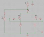
Frags posted a couple of SCH for differential testing in 9 December
Tanks again to Frags for ideas and help.
The 2 first pictures are his original work.
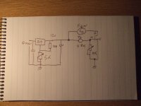
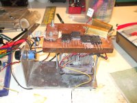
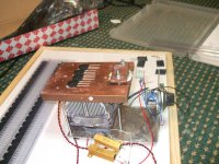
I have made up a little test rig with a CPU fan and a simple controller.
Just parts I had already and quite suprised on how well it works
may be handy as fan speed contreller later on.
It can dissipate well over 50W (done my matching at 26V and 2A) and keep temperature whiten + - 1 C of the 50 C I picked out of the hat.
While I measure one duda the next few are sitting on the plate getting worm.
I get Vgs to settle in a minute or so and at 50 C the effect of ambient temperature and air currents is greatly reduced.
Maybe at 30 C one may risk corrupting results Just by touching the little Bug...
QSP is doing same much more advanced testing and he posted a SCH for Tran conductance matching.
Although next on my list of to do things I have not tried that one out
But well worth a look at (just search for QSP posts as at the moment I have lost it)
http://www.diyaudio.com/forums/swap-meet/182480-holco-mfr-15ppm-2w-sale.html
Frags posted a couple of SCH for differential testing in 9 December
Tanks again to Frags for ideas and help.
The 2 first pictures are his original work.
I have made up a little test rig with a CPU fan and a simple controller.
Just parts I had already and quite suprised on how well it works
may be handy as fan speed contreller later on.
It can dissipate well over 50W (done my matching at 26V and 2A) and keep temperature whiten + - 1 C of the 50 C I picked out of the hat.
While I measure one duda the next few are sitting on the plate getting worm.
I get Vgs to settle in a minute or so and at 50 C the effect of ambient temperature and air currents is greatly reduced.
Maybe at 30 C one may risk corrupting results Just by touching the little Bug...
QSP is doing same much more advanced testing and he posted a SCH for Tran conductance matching.
Although next on my list of to do things I have not tried that one out
But well worth a look at (just search for QSP posts as at the moment I have lost it)
http://www.diyaudio.com/forums/swap-meet/182480-holco-mfr-15ppm-2w-sale.html
Attachments
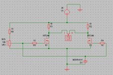
Vgs is better generated with a stabilized voltage. I used an LM317.
Using the LM317 I was able to match sextets out of a batch of 50 to within 2% of each other.
Using the LM317 I was able to match sextets out of a batch of 50 to within 2% of each other.
After the matching process I now have 26 x IRFP244s left over.
These have all gone through the matching process and will be supplied with the relevant data to enable you to pick out matched pairs and triplets.
£50.00 the lot plus P&P.
These have all gone through the matching process and will be supplied with the relevant data to enable you to pick out matched pairs and triplets.
£50.00 the lot plus P&P.
Last edited:
- Status
- Not open for further replies.
- Home
- Amplifiers
- Pass Labs
- Matching IRFP244 MOS-FETs