Many questions! How important is the match between diodes in a ratio detector? I'm talking your typical FM tuner here. Assuming it is, what's the best way to do it. I can certainly do it on a curve tracer, but it seems logical that a diode used in an RF circuit would be matched in some kind of RF bridge at the operating frequency. All manner of mixers and modulators seem to need matched diodes, but I can't find anything on how it's done or typical circuits to do it.
G'day mate, as I understand it the ratio FM detector is less commonly used these days however diode matching may be desirable.
Simply matching the forward voltage drop will most likely be sufficient. Using a low noise (silicon schottky) pair of diodes is likewise probably worthwhile. Regards, Felix (vk4fuq).
Simply matching the forward voltage drop will most likely be sufficient. Using a low noise (silicon schottky) pair of diodes is likewise probably worthwhile. Regards, Felix (vk4fuq).
Imperfect matching will increase even-order distortions and require an offset from the center frequency of the tuned circuit. Nothing catastrophic, but if you aim for the top quality, it is best avoided.Many questions! How important is the match between diodes in a ratio detector?
Since the diodes are of the same type, they will already share a good number of characteristics, thus a static matching should normally suffice: measure the Vf at some representative current(s). For this kind of application, the current will be lower than the typical test current of a multimeter. Something like 100µA would be preferable.I'm talking your typical FM tuner here. Assuming it is, what's the best way to do it. I can certainly do it on a curve tracer, but it seems logical that a diode used in an RF circuit would be matched in some kind of RF bridge at the operating frequency.
You could make measurements at 30µA and 300µA for example.
If you use Ge diodes, you should also check the leakage current as it can vary significantly from part to part and have influence at low levels.
Note that it is probably still possible to find prematched sets, like the 2-AA119
Thanks! I may never fully understand RF stuff, but I'm looking for all the reasons that optimum distortion, maximum signal strength reading and centered tuning (meter) sometimes don't occur in the same place during an alignment. I'm guessing classic receiver makers didn't use matched diodes (or other parts), and that some optimization could be beneficial.
Something even odder is that Marantz biased their detector off zero (model 2230 and others) by about 0.36 VDC. Following their instructions to tune to zero volts simply doesn't work and results in a lousy alignment.
I finally found one on-line reference that said diodes could be matched by rectifying 10.7 MHz and loading the diode with 10 kohms and 0.1 uF, then selecting diodes that produced the exact same DC voltage. I can imagine setting this up with two, just like a bridge, and looking diode pairs that produced a difference of 0 VDC. I'll have to do some experiments to see how well this agrees with low current DC matching.
A DC match is probably sufficient.
If you get funny detector alignment problems then check the electrolytic which usually sits across the 'DC' end of the detector. If this has gone low or leaky then it will cause trouble. It is a particular problem in valve circuits, as the heat dries it out.
If you get funny detector alignment problems then check the electrolytic which usually sits across the 'DC' end of the detector. If this has gone low or leaky then it will cause trouble. It is a particular problem in valve circuits, as the heat dries it out.
I think they did: in the sixties and seventies, Philips which was far from a high end brand proposed the 2-AA119 in its semiconductor selection, and they did use it in their reference designs (and probably in their receivers)I'm guessing classic receiver makers didn't use matched diodes (or other parts), and that some optimization could be beneficial.
There is always a "structural misalignment" caused by the non ideal quadrature phase shift of the auxiliary winding.Something even odder is that Marantz biased their detector off zero (model 2230 and others) by about 0.36 VDC. Following their instructions to tune to zero volts simply doesn't work and results in a lousy alignment.
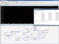
Such an effect appears even in sim, see below.
Out of curiosity, I quickly checked the effect of a mismatch in sim: it is pretty crude as I used the first values that came to mind for the Q's, coupling coefficients, etc, and the simulated mismatch is equally gross: one if the diodes is simply duplicated.I finally found one on-line reference that said diodes could be matched by rectifying 10.7 MHz and loading the diode with 10 kohms and 0.1 uF, then selecting diodes that produced the exact same DC voltage. I can imagine setting this up with two, just like a bridge, and looking diode pairs that produced a difference of 0 VDC. I'll have to do some experiments to see how well this agrees with low current DC matching.
The effect is rather dramatic, with the THD going from 1.8 to 2.7%, which might be expected for such a brutal change, but of course the initial THD was already large to begin with.
In addition, duplicating a diode means lowering its Vf by ~19mV, which is not that large after all.
This example is to be taken for what it is worth and no more obviously....
Attachments

Thanks! That's a very clever way of mismatching the diodes- never would have thought of it. I'd assume that keeping matched diodes at the exact same temperature is important, and that's not a given on any particular PCB.
DF96- just for fun I pulled the cap and checked it. Not as good as a brand new one for loss (D a bit over 0.1 at LF), so I replaced it, but it made no difference in the circuit. Still, most of what I work on can be considered elderly, so all parts are suspect.
DF96- just for fun I pulled the cap and checked it. Not as good as a brand new one for loss (D a bit over 0.1 at LF), so I replaced it, but it made no difference in the circuit. Still, most of what I work on can be considered elderly, so all parts are suspect.
Last edited:
In the past it was common to find matched Germanium diodes, and even quads. I used Tungsram OA1154-Q in a double balanced mixer circuit. Silicon diodes are not so good for low level RF.
My diode collection includes 1N270, 1N34 and some HP Schottkys that might be suitable. No idea which is really better, but I lean towards the 1N270 parts.
- Status
- Not open for further replies.
- Home
- Source & Line
- Analogue Source
- Matching diodes for ratio detector- how?