Hi here.
I know it's the wrong place, but i also know that we sometimes need matched transistors for our beloved Pass amp.
Well, long story short; i need to match two "complimentary" transistors, excatly BCP53T which is PNP / https://assets.nexperia.com/documents/data-sheet/BCP53T_SER.pdf with an BCP56T (NPN) https://assets.nexperia.com/documents/data-sheet/BCP56T_SER.pdf
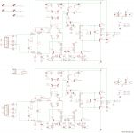
I need to match T8A with T9A and T8B with T9B on the attached schem.
The thing i build is an class-A outputstage for a DAC i am building Arduino controlled Dual Mono AK4490 DAC (Part 3) | Dimdim's Blog
So the description (which ofcause also can be read in link) of biasing the circuit is as this :
I was hoping that someone here could point me in the right direction, howto match those transistors for the circuit?
I also attached a schematic from Sound.Elliot which i intend to use maybe for this.
Matching Power and Driver Transistors
I hope i got it explained right, otherwise please ask 🙂
Best regards; Jesper.
I know it's the wrong place, but i also know that we sometimes need matched transistors for our beloved Pass amp.
Well, long story short; i need to match two "complimentary" transistors, excatly BCP53T which is PNP / https://assets.nexperia.com/documents/data-sheet/BCP53T_SER.pdf with an BCP56T (NPN) https://assets.nexperia.com/documents/data-sheet/BCP56T_SER.pdf
I need to match T8A with T9A and T8B with T9B on the attached schem.
The thing i build is an class-A outputstage for a DAC i am building Arduino controlled Dual Mono AK4490 DAC (Part 3) | Dimdim's Blog
So the description (which ofcause also can be read in link) of biasing the circuit is as this :
Power should be ideally +/-16VDC. A bit less is OK. The board is running in class-A so current draw is constant. A power supply with 100mA current capacity should be enough.
Bias current is adjusted by the multi-turn trimmers R26A and R26B. They should be adjusted to their mid value before soldering to the board (~1K). To adjust bias just measure current consumption at one of the rails while turning the pot. Adjust for ~25mA total current draw per rail and per channel. Current draw on the negative rail should be about 1mA higher than on the positive rail.
I was hoping that someone here could point me in the right direction, howto match those transistors for the circuit?
I also attached a schematic from Sound.Elliot which i intend to use maybe for this.
Matching Power and Driver Transistors
I hope i got it explained right, otherwise please ask 🙂
Best regards; Jesper.
Attachments
Last edited:
I bought one of these the other day. I can't prove if the Hfe is accurate or not, but it seems good with everything else it does.
https://www.amazon.com/Transistor-DROK-Capacitor-Capacitance-Automatic-x/dp/B01MS1FOYM
https://www.amazon.com/Transistor-DROK-Capacitor-Capacitance-Automatic-x/dp/B01MS1FOYM
Thanks...
I will try to find some appropiate tester somewhere here in DK
Have a' nice day out there... Jesper.
I will try to find some appropiate tester somewhere here in DK
Have a' nice day out there... Jesper.
I bought one of these the other day. I can't prove if the Hfe is accurate or not, but it seems good with everything else it does.
https://www.amazon.com/Transistor-DROK-Capacitor-Capacitance-Automatic-x/dp/B01MS1FOYM
I've got one similar and have compared it to a calibrated Tektronix 576.
Surprisingly, pretty close Hfe measurements. (5%)
- Status
- Not open for further replies.