Look at the Zeners,Bottem righ....
This what sets up the Bias,it at allmost 5500-vWith out the Zener string
Reg.to ground.
If you go up to much with the ML panels, You hear a buzz, just back off.Same as my Soundlabs you here the buzz back of a little...
Mr Powers gave Me the info...an i did this MOD, it works...As you see ....Eze..
As you see there are two RE. r23-r24 1.8k in the feed to the bias tranfourmer on the AC side....this well give more aswell, Just jumpr23-r24 an you go to allmost 4000-v.. From The stock of 3700-v....Have Fun Price$$$$ your time.
Attachments
Last edited:
I have bypast the SL3 bias board .
Put in the Ajustabl bias for my Acoustats, now i can go from 3.5k to 6.5k Thay now can be set up to mach the bass driver much better an there at 4.3k sounds better than ever.
One thing the bias add too the sound of the panel.... Most dont talk about this,so the by-pass cap mod can help tune the tone...mod is to go from ground to the end of the diode string be for the 50m re. that feeds the panel...Cap .01 5k...or higher
Mod for Bias tone
I have dropet the 50m to 6m sounds better.....An have added 2more caps an 2more diodes.....i have found the Acoustats stock bias boards are off now that there 25-30years old...Or the panels or diff.
In my setup i have add a new bias tranfourmer at 1100v before the diodes the stock Acoustats are at 7500v....
Thanks for the Pix.... lzzy wizzy Audio...looks like something i would do if i could....an thay say i am a acoustat nut...Moray J. may give us his Chok mod...cant find?
Attachments
![ehtmoda[1].gif](/community/data/attachments/223/223479-0e2875b11bba73b6fc69e40ec48d48bd.jpg?hash=Dih1sRu6c7)
![frame_l[1].jpg](/community/data/attachments/223/223490-108bf84a3588d976fd1eab4dc45802f9.jpg?hash=EIv4SjWI2X)
more bias
Look at the SL3 power sip... R21-R25.....these are 15m ohm X4 60m........this panel is 12"x48".....these need to be replaces....thay are 1/4w....i have went to 1ea 5mohm.. 5wat there..sound is much faster... a it look like that going from 3k bias to 3.5-3.7/5...is the sweet spot...but the stock bias tranfourmer in the MLs is about a 1amp.....i have put a 8amp.... what a big diff...same bias-v...sounds 3db louader....Bass starts at the top...
One sided bias feed there still useing....sale them panels..
But these ML are a steal....panels can be Diyed... an the powtercating can take 5kbias...eze Here a Panel with two bias feed FIX..
Attachments
![12[1] (3).jpg](/community/data/attachments/227/227051-3ae98696891c9e81708f4df185c1584e.jpg?hash=OumGlokcno)
![2[1] (2).jpg](/community/data/attachments/227/227075-9eb9cd69fdb0b944c6efb28c1214ed5b.jpg?hash=nrnNaf2wuU)
![2008_0408self_pics0148_small[1].JPG](/community/data/attachments/227/227095-e8086611831d2183d390bf6a10360258.jpg?hash=6AhmEYMdIY)
![4[1] (5).jpg](/community/data/attachments/227/227103-b8cd8a1a2b1e8137878fd4a48a65f710.jpg?hash=uM2KGisegT)
Ascent
Just got these of CL for $100.US.....i well have pix after there playing.. there out there the panles are like new....after a bath...here how thay lookt in the add...This is killing my diy ESLs.....
Just got these of CL for $100.US.....i well have pix after there playing.. there out there the panles are like new....after a bath...here how thay lookt in the add...This is killing my diy ESLs.....
Attachments
![5O25Z35S43n23k53l8bbg2d5edfe5b79e13b4[1].jpg](/community/data/attachments/231/231204-ea881986dd20bb00c30794e94b47f2a3.jpg?hash=6ogZht0guw)
![5P65X35S13nc3k63ldbbgb8730ad7f0c71472[1].jpg](/community/data/attachments/231/231205-d5fd61c93c5e51b738f500a6160c8ed0.jpg?hash=1f1hyTxeUb)
![5V15Q35Z43nb3p03o1bbge4befe66d39f119e[1].jpg](/community/data/attachments/231/231207-896955481f8a1707b3f9bf22d76d5ed1.jpg?hash=iWlVSB-KFw)
Here the best way to opnen up the sound of the panels on the logans....On the power/bias board...Run a wire from in front of the jumper to r25 this leves r25 with a 15mohm an well sound like new panels.New Day for the older....ML
Get the bias up an noise out!
Well as time gos by thing change....we no this but.....Look at this setup here now...thay have tied all the setup thransfourmer outputs AN THE BIAS FEED FROM THE BOARD..to the panel with the AC..comeing in from the the manes..120ACv...Noise any one.....get that out for better sound...an look at the panel feed on top of the tranfourmer....that only rated for a 1kv...it drops the bias feed DOWN by about 500DC V....it should be 3500-v..not 3000....just moveing that well give better sound!
Well as time gos by thing change....we no this but.....Look at this setup here now...thay have tied all the setup thransfourmer outputs AN THE BIAS FEED FROM THE BOARD..to the panel with the AC..comeing in from the the manes..120ACv...Noise any one.....get that out for better sound...an look at the panel feed on top of the tranfourmer....that only rated for a 1kv...it drops the bias feed DOWN by about 500DC V....it should be 3500-v..not 3000....just moveing that well give better sound!
Attachments
Last edited:
Any suggestions for possible tweaks or mods on the boards shown in the post above are greatly appreciated! Also, does anyone know the purpose of the switch shown in the bottom right of the bias board? It has two positions: "0" and"1" but has always been on "0".
Other mods I have done on the Sequels have been structural. Based on posts on the net several years ago showing resonance in the bass cabinet and "wings" behind the panels, I fashioned braces made from 1" galvanized pipe filled with sand. One goes between the wings and one goes from either side and to the rear of the bass cabinet using a pipe T. This cleaned up the bass and midrange clarity. I also removed the batting in the bass cabinet and installed a sorbothane deflector on the rear wall of the cabinet. This had the effect of making the bass sound quicker and more impactful.
Other mods I have done on the Sequels have been structural. Based on posts on the net several years ago showing resonance in the bass cabinet and "wings" behind the panels, I fashioned braces made from 1" galvanized pipe filled with sand. One goes between the wings and one goes from either side and to the rear of the bass cabinet using a pipe T. This cleaned up the bass and midrange clarity. I also removed the batting in the bass cabinet and installed a sorbothane deflector on the rear wall of the cabinet. This had the effect of making the bass sound quicker and more impactful.
Also, does anyone know the purpose of the switch shown in the bottom right of the bias board? It has two positions: "0" and"1" but has always been on "0".
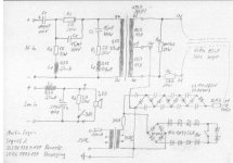
Martin Logan uses a string of zener diodes inside of a bridge rectifier to regulate the output of the bias supply transformer which is fed to the HV multiplier. The switch is in the lower right corner of the attached schematic.
When the switch is in position "1", it is closed and bypasses two of the zener diodes which would lower the regulation voltage and thus the output of the HV bias supply relative to the "0" position. I don't know what value zener diodes are used, so couldn't tell you exactly how much the HV would be affected. This might have been used to slightly adjust ESL panel output if neccessary to get better matching between left and right speakers in a given pair.
Attachments
Last edited:
Schematic
Thank for the schematic.
Rob you can see that the tranfourmer is in the pushpull setup...
Looks like the 20w5k well cut the output of the panels...An the 100k 50watt
You can take them out ...this well give better bass...an open up the sound... if you like the sound of them in, a new diff res. there ,can give a better sound...
The SL3 an Ascent Tranfourmer is diff than the Sq...but thay use nothing on that side of the tranfourmer..here is the Ascent schematic
An the limiter dose not come on the sean...till the late SL3.. i have had 2pr of SL3s here that did not have the limiter in them..
Thay did this same thing to the older CLS, it some type of tone seting that jim said thay did away with...I have pulled out these res. an got much better sound...Hoho
Attachments
MoDs Why?
Some May say Why Mod the MartinLogans....thay sound great as thay are..
Here what i say ....Yes thay can be some of the best ESL out there..But...
I now have a Pr of Prodigys here now...stock thay sound ok...for a 10k pr of speakers....if you drive the with a big amp...an big bucks..wire,tube pramps..
But with small mods the Prodigys can fill a room 18'x27....with a 60watt tube amp...mods.... Panels....got to get the Bias feed to the panels.. with the logans at lest bias on the left an right side of the panel.... Bias...some how we forget the bias IS the ESL.. it what sets the sound of any ESL...10k speakers with a $20 bias an limiter board.....An then the Limiter...had people here that let hear the Limiter in....an out....all said the highs were much better with it out...I well say that if all i did was pull the limiter out of
the stock Speakers it would not be AS eze to spot...but with the mods ...it night an day... the limiter dose not sound bad..it rolls the vary top down...
look at the frist Limiter on the bottem...not a bad looking deal... but Look at the top one were it all on the bias board....cost them maybe $20..for the board...way diff.....this is in the Prodigys....an if you to get a amp an drive it in to cliping all the time the limiter is for you...or you have a hard to drive full rang ESL it may work for you...but most dont need this ever..
MartinLogan can sound Sweet an big an full like the best soundLabes ...But thay can also ROCK the House....My SL neever did this.
All this is just MY O-pine..thanks
Attachments
![ML%20DEC-4%20pcb%20small[1].jpg](/community/data/attachments/226/226463-6cc1ddeeefa63467fad29db227aafcde.jpg?hash=bMHd7u-mNG)

Moray
I sent you a misage....but your full ....You an yours...have a happy hoho...
An Too all other Exotics..........
I sent you a misage....but your full ....You an yours...have a happy hoho...
An Too all other Exotics..........
Check my logic here
C1 and R2 in the Sequel II schematic (offered in a post above) are the only components where signal has to directly pass through on the Hi Freq side of the crossover. I am assuming that means these are the only two that therefore need to be very high quality and tuned by ear. For instance, changing out the other caps, etc will have a marginal, if any, affect on the sound quality.
Is this correct?
Thanks for your input.
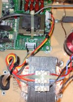
Pic of Completed Bias Mod
Here is a pic of the completed bias mod on my Sequel IIs as suggested by Tyu. As you can see, a jumper wire has been soldered between the last diode and the last resistor, removing the other three 16mf resistors from the circuit. As mentioned in an earlier post, the improvement of just inserting this jumper was significant. Better clarity and immediateness. As you can see, there is one 16mf resistor remaining in circuit prior to the output of the board and I replaced this old carbon comp with a 10mf Dale metal film resistor. The metal film made a subtle difference in the same direction as the jumper.
Here is a pic of the completed bias mod on my Sequel IIs as suggested by Tyu. As you can see, a jumper wire has been soldered between the last diode and the last resistor, removing the other three 16mf resistors from the circuit. As mentioned in an earlier post, the improvement of just inserting this jumper was significant. Better clarity and immediateness. As you can see, there is one 16mf resistor remaining in circuit prior to the output of the board and I replaced this old carbon comp with a 10mf Dale metal film resistor. The metal film made a subtle difference in the same direction as the jumper.
An externally hosted image should be here but it was not working when we last tested it.
Effect of R5, R4 and a question.
Hi,
thanks Bolserst (and Calvin) for the circuit and Rob, Tyu for your posts.
My findings concerning Sequel2:
Ommitting R5 results in the highs being raised beginning from 8-9 kHz.
At 20 kHz they will peak more than 10 dB above the rest.
For me, it sounds too hot. Paralleing R5 with the same value and therefore halving the resistance, should be more balanced.
R4 lowers the efficiency of the whole panel about 4-5 dB. Ommitting this will result in a lean sound. Might be OK, if you place the speakers near the wall.
I took measurements, but unfortunately, didn't store them on my PC.
What's not clear to me: putting the resistor (R5) before one stator, should raise distortion, because the force to the foil will be not equal from front and back stator.
What do you think?
Negligible?
Maybe it could be prevented, by putting resistors before both stator sides, right?
regards
Olaf
Further tip for the SL2
Hi Rob,
have you tried this:
http://www.diyaudio.com/forums/planars-exotics/172192-what-amplifier-driving-esl.html#post2280219
Regards
Olaf
Hi Rob,
have you tried this:
http://www.diyaudio.com/forums/planars-exotics/172192-what-amplifier-driving-esl.html#post2280219
Regards
Olaf
- Status
- Not open for further replies.
- Home
- Loudspeakers
- Planars & Exotics
- MartinLogan Bias Mod