OT:
The master volume potentiometer is 4,7KB = Linear. The amp gets loud really fast. Playing with the idea to replace it with log/audio type with same value.
The master volume potentiometer is 4,7KB = Linear. The amp gets loud really fast. Playing with the idea to replace it with log/audio type with same value.
the signal looks like rectification current peaks, inductively coupled into the signal chain ?
I once had a popping amp, and that turned to be the ceramic cap collector to base of the VAS stage. never thought that ceramic caps could fail but the voltage there has full swing 90V.
I once had a popping amp, and that turned to be the ceramic cap collector to base of the VAS stage. never thought that ceramic caps could fail but the voltage there has full swing 90V.
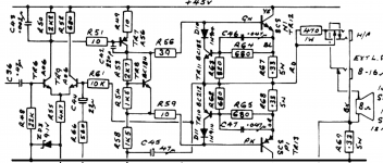
also ZD3, the zener could be noisy..
hard to tell if the C42 cap is OK or not, replace by 500V type
hard to tell if the C42 cap is OK or not, replace by 500V type
Not "theory" ideas.@JMFahey Any other ideas? 🙂
Hands on, I would try nearby grounding points, often 1 inch away means a lot ... but you have to find that point.
Still believe, and basreflex apparently too, that those are capacitor charging pulses.
Although I think them resistive generated rather than inductive coupled.
2 experiments:
1) lift one leg from C36 to check whether hum/buzz is self generated or comes from preamp. Any change?
2) ground TR6 Base//R48(top) node with a piece of wire straight to the supply capacitors point where PT CT returns.
Any change?
ground
if it was inductive , indeed the hum signal shape would be different, so lets look at resistive first.
looking back at some pics near the rectifier, I would say that the plus and minus of the rectifier should be wired directly to the caps, right on the pins, and from there to the rest of the amp. put the voltmeter in ac mv mode and measure the rails ripple voltage.
looking back at some pics near the rectifier, I would say that the plus and minus of the rectifier should be wired directly to the caps, right on the pins, and from there to the rest of the amp. put the voltmeter in ac mv mode and measure the rails ripple voltage.
interestingly, the schematic has the same manual drafting style as the schematics from the "Quad" brand. (acoustical manufacturing company huntingdon)
@basreflex
- replaced the cap, no change
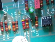
- ripple on the power resistors R44-47 starts on 8mV and settles on 0,4 mV, most probably not reliable measurement
- zener was checked in circuit the zener voltage is in spec, do not have replacent to check if it is noisy
- marshall reverb 30 from the same series has also handwritten schematics
- replaced the cap, no change
- ripple on the power resistors R44-47 starts on 8mV and settles on 0,4 mV, most probably not reliable measurement
- zener was checked in circuit the zener voltage is in spec, do not have replacent to check if it is noisy
- marshall reverb 30 from the same series has also handwritten schematics
@JMFahey
- removed C36, noise flow lowered, buzz lowered and the structure was different, but it was not so clean like when I push connector in the RETURN input
- grounding the TR6 base = R48 Top the the main filter caps grounding point, lowers the hum/buzz significantly, but it is still present in the background
These are all highly "subjective" observations.
could you expand a little on the observation "but it was not so clean like when I push connector in the RETURN input"?
Interesting/weirdish.@JMFahey
- removed C36, noise flow lowered, buzz lowered and the structure was different, but it was not so clean like when I push connector in the RETURN input
*Sometimes* you remove a hum source and hum *increases* 🙁
because you have multiple hum injectors and the one you removed was out of phase and (partially) cancelling others.
This shows some future: lift grounded (bottom) end of R48 and send it (you already have the wire available) straight to main caps centerpoint (one wire end is already there):- grounding the TR6 base = R48 Top the the main filter caps grounding point, lowers the hum/buzz significantly, but it is still present in the background
Any change?
I expect lowered noise level, perhaps not as lowered as straight grounding the input but every bit counts.
IF you feel adventurous, try grounding the supply end of the added cable to different points, say nearer the top cap, nearer the bottom one, etc. , you might find a "sweet spot".
No magic involved at all, simply we can not see a "map" of currents and hum voltages running in that area, too low for conventional meter, but ear might find a slightly better grounding point.
No, nothing subjective in comparing hum levels, even better seeing waveform and peaks in a scope screen.These are all highly "subjective" observations.
Subjective is all the audiophool cr*p, undefinable properties which can not be confirmed, here we are just running just below the threshold of needle or digital meters.
And even so, if really needed, I (or anybody else) could build a sensitive preamp, battery fed so as to make it fully independent, and a set of adjustable "needle" test probes to measure *small* voltage differentials between nearby chassis points, across a crimped connector, even across a soldered joint, etc.
Long ago I built just that, to measure voltage drop across plug/jack interface, riveted to chassis ground terminals, etc.
Should build a modern version, a floating differential probe sending microvolt waveforms to scope , would be the useful here.
@turk 182 have repeated the test with fresh ears in early morning, removed cap has exactly same buzz level as shorted plug inserted into return jack.
Sorry for confusion.
Sorry for confusion.
@JMFahey
'These are all highly "subjective" observations.' was more related to the fact that I am comparing buzz levels with my ears a not via scope/analyzer.
Your advice is of course objective.
'These are all highly "subjective" observations.' was more related to the fact that I am comparing buzz levels with my ears a not via scope/analyzer.
Your advice is of course objective.
Last edited:
Couple of iterations and experiments happened in between. No breakthrough, no improvement. Assembled the amplifier and will play it for couple of weeks until the parts arrive (waiting until my supplier backorders "marshall" alpha pots). Want to replace boost channel gain pot and master volume pot.
Last edited:
Here's hoping I read all the posts correctly.
Perhaps when you are tinkering next, can you confirm what is in post #5, that when the return input is used, or shorted to gnd, you effectively get no hum?
Going back one stage, one leg of C33 would be temporarily lifted, although post #61 indicates it is factory removed. If so, then a better isolation test would be to lift one end of R36 and short the pot wiper side of R37 to IC5:5 with a link.
Imho, the location of the hum ingress needs to be initially narrowed down as much as possible.
Hi @trobbins,
when the RETURN is used the hum/buzz is attenuated to level which can be described as "happy to have".
The C33 and L6 jumper were most probably removed in factory (seen that mod in pictures of other units and even tried to revert it -> the result was more buzz).
when the RETURN is used the hum/buzz is attenuated to level which can be described as "happy to have".
The C33 and L6 jumper were most probably removed in factory (seen that mod in pictures of other units and even tried to revert it -> the result was more buzz).
Attachments
Last edited:
Ta. Other plausible tests for localising the noise source with respect to IC5b stage would be to:
- short the C34/R38 node to gnd.
- swap out IC5 (either for another 1458P or a TL072)
- and the post #96 check.
There are lower noise dual opamps than the 1458P, such as OP270, if you find your happiness with noise unquenched (although I'm not sure about robustness).
- short the C34/R38 node to gnd.
- swap out IC5 (either for another 1458P or a TL072)
- and the post #96 check.
There are lower noise dual opamps than the 1458P, such as OP270, if you find your happiness with noise unquenched (although I'm not sure about robustness).
- Home
- Live Sound
- Instruments and Amps
- Marshall Reverb 75 (5275) - Hum issues