I get superloud buzz when I try to short the pin 6 on IC5 after R37. The C33 in schematic is not installed in my version (factory mod).
IC5 is also touch sensitive with all controls on zero. Reverb tank is not connected.
IC5 is also touch sensitive with all controls on zero. Reverb tank is not connected.
ah crap yet another condition that is out of observational control sorry i should learn when to bow out...where's me scotch...
Please: what DC mV do you keasure at speaker out?
What AC mV same place.
Please measure AC both ways, your multimeter should have a 200mV AC scale or it won´t do.
Measure both ways (inverting probes) and post both results, because DC offset may cheat the meter.
Do you have a scope?
Please show an image of Hum/Buzz and some kind of scale, so we can check both waveform and PP value.
If not, we´ll be here until the end of Quarantine (meaning MANY Months) 🙁
@JMFahey
Following values were measured on amplifier without connected speaker and removed from box:
- DC offset starts on approx 79mV and slowly crawls up as it warms up. After 8 minutes it was on 115mV, still increasing slowly
- AC voltage measured both ways is the same 18mV (my DMM has 60mV range)
No scope currently. But I can try to measure it with laptop, REW has also scope feature. The wave form should be the same on the attenuated headphones output, or I will use the speaker as load.
Thanks.
DC offset is highish but still very normal, within parameters.
AC voltage might be lower but doesn´t look like uncontrolled unbearable hum to me.
Detectable in a house room setting, doubly so at night, will definitely dissappear in a rehearsal room after the first cymbal crash (when ears in self defense trigger the 20 dB pad he he) and even in a "silent" Club stage, just because of background noise which will cover it.
My point being (from the beginning, reading your description) that maybe you do not have a sick or broken amp, but a normal 80's one designed for live sound.
And it IS a LOUD beast.
Power is fine, and speaker is a beast, a 103dB Celestion made EV clone, complete with a huge magnet (much larger than that in an already loud Vintage 30), edgewound Aluminum voice coil, the works.
That said, if at all possible, show us the output waveform; 50mV 50Hz sinewave is inaudible, 50mV 100 Hz ripple sawtooth is annoying, 50mV average wild waveform buzz may be unbearable.
A software scope capture is fine, we want to see waveform, measurement was already sort of covered.
I wouldn´t expect nothing nastier than some ripple but, hey, testing rules.
well if the reverb pan is disconnected and he has not turned the reverb control off it will add noise.
it's all conjecture and supposition based on someone else's perhaps inaccurate observation and test methodology.
it's all conjecture and supposition based on someone else's perhaps inaccurate observation and test methodology.
@JMFahey agree to all of your arguments.
I have never mentioned that the buzz is unbearable, it is just annoying which is mostly caused by the 150Hz harmonic.
The sole reason why it is percieved "louder" than usual is most probably higher speaker sensitivity.
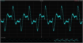
Attaching the wave form measured on headphones output.
I have never mentioned that the buzz is unbearable, it is just annoying which is mostly caused by the 150Hz harmonic.
The sole reason why it is percieved "louder" than usual is most probably higher speaker sensitivity.
Attaching the wave form measured on headphones output.
Attachments
Replaced differencial transistors pair (TR6,TR9 = MPSA06) with matched pair (just same hfe from same tape, no Vbe matching) which improved dc offset behaviour in positive way.
It is more stable now and it did not crawled over 80mA during testing period. Fluctuates between 75 an 80 mV.
The original pair had hfe 43 and 355.
It is more stable now and it did not crawled over 80mA during testing period. Fluctuates between 75 an 80 mV.
The original pair had hfe 43 and 355.
Oh, I added the "unbearable" possibility to the Menu, just to cover all grounds 🙂@JMFahey agree to all of your arguments.
I have never mentioned that the buzz is unbearable, it is just annoying which is mostly caused by the 150Hz harmonic.
Yes, that´s one valid point.The sole reason why it is percieved "louder" than usual is most probably higher speaker sensitivity.
Thanks, now we are talking on more solid grounds.Attaching the wave form measured on headphones output.
It falls as you noticed into the "somewhat annoying" type, not simple sawtooth ripple (so no dry/dead capacitors to be blamed) and luckily no instability/oscillation involved (which is the unbearable kind), nor even feedthrough from some channel which "should" be muted, to my eyes and by its frequency and waveform it´s grounding based.
Some audio return path ground is being contaminated by main capacitors charging pulses, which are narrower duty than 50Hz half sinewave width, since capacitors only charge when peak winding voltage is higher than capacitor stored DC voltage, that shows in the narrow taller peaks.
Been designing and manufacturing guitar amps for a long time, fighting this buzz is part of the debugging stage.
Solutions are semi-empirical, often grounding something here is problematic, doing same 1 inch away solves it.
Black magic?
Not at all, but these problems often involve invisible for us ground currents, and hard to measure tiny voltage drops.
I suggest you remove the power transformer center tap wire from its current grounding spot (it probably goes through a connector and a piece of track) and solder it straight to the center of the copper area joining both main filter caps.
It should minimize that residual hum in general and those peaks in particular.
Has anyone tried to determine if noise is coming from preamp or power amp section?? Couldn't you short output of IC5 pin 1 to ground and determine that? If preamp induced should decrease dramatically if not it is originating in power section?? At least figure which section to work with.
@Freecrowder ... yep we tried it is mentioned in previous posts. The buzz is introduced somewhere in the last stage of preamp. Not in power amp and not on the very beginning.
Even closer.
Look UNDER the PCB, there must be some thick copper joining one cap positive to other cap´s negative, that is "the Mother of all Grounds" he he, the point with lowest resistance/impedance to supply ground, the ACTUAL supply ground.
Solder center tap there and you´ll minimize charging pulses contaminating everything else.
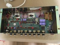
To prove "I do what I preach" here´s my bread and butter 100W Bass Amplifier, sold over 14000 of them in over 50 years, every detail is "proven in combat" and then some.
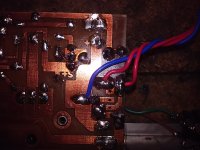
Showing first PCB from above (like your picture) and then from below.
Main caps are not touching each other (layour needs) but joined by a sea of copper, about center you´ll see within 5mm of each other: chassis ground wire, main input and preamp wire, and most important both high current "customers": Speaker return and transformer center tap, which was soldered last to the "all grounds together" blob.
THERE IS a 3 pin .156 pitch AMP connector pad array in the PCB, in case I need it to be plug-in (often in some powered cabinets or monitors) but if at all possible (like here) I avoid it and straight solder to PCB bottom, minimizing everything.
Solder beats connectors any day of the week.
Look UNDER the PCB, there must be some thick copper joining one cap positive to other cap´s negative, that is "the Mother of all Grounds" he he, the point with lowest resistance/impedance to supply ground, the ACTUAL supply ground.
Solder center tap there and you´ll minimize charging pulses contaminating everything else.
To prove "I do what I preach" here´s my bread and butter 100W Bass Amplifier, sold over 14000 of them in over 50 years, every detail is "proven in combat" and then some.
Showing first PCB from above (like your picture) and then from below.
Main caps are not touching each other (layour needs) but joined by a sea of copper, about center you´ll see within 5mm of each other: chassis ground wire, main input and preamp wire, and most important both high current "customers": Speaker return and transformer center tap, which was soldered last to the "all grounds together" blob.
THERE IS a 3 pin .156 pitch AMP connector pad array in the PCB, in case I need it to be plug-in (often in some powered cabinets or monitors) but if at all possible (like here) I avoid it and straight solder to PCB bottom, minimizing everything.
Solder beats connectors any day of the week.
Attachments
Last edited:
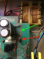
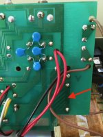
Will try to move the center tap here (red arrow), or did you meant different location with "even closer"?
Attachments
Last edited:
Moved the center tap connection to the point marked by arrow in previous post. No change in the hum-buzz floor.
Last edited:
Ok. It was worth a try though.
Side note: that is a WEIRD Layout/PCB and that might explain both the residual hum/buzz and the connection displacement not solving it.ñ
Notice mine (what also 90% of designers do) where if possible main caps are side by side as in yours, seen from above , (in mine that was not possible for other reasons), but one positive and one negative (grounded ones) are joined by a least resistance path, either a short stubby track or (my case and others) a wide copper *area* , period.
The more copper the merrier 🙂
Strangely, in yours capacitors appear to be radial (same as mine and most others) but instead of being inserted straight down in pads one leg does so, the other is open sideways and travels *above* the PCB to its pad, 1 inch or more away, through thin *iron* legs.
They even had to insulate them and of course caps do not sit snugly against PCB which needed extra bracing and gooping.
Not the lowest resistance ground path to be sure, and probably leading to the residual hum/buzz you see.
Sorry.
The "weird" capacitors installation is not the cause of residual hum. They were installed by me, because I was not able to order quality axial capacitors fast enough before holidays. No change in hum/buzz after the radial caps installation compared to original.
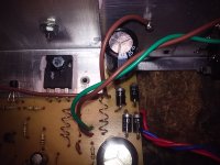
The whole pcb was designed for axial electrolytics caps. Attaching pic of original caps.
The whole pcb was designed for axial electrolytics caps. Attaching pic of original caps.
Attachments
Last edited:
- Home
- Live Sound
- Instruments and Amps
- Marshall Reverb 75 (5275) - Hum issues