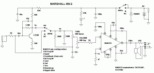
Hi, I'm looking for a tested marshall ms-2 circuit diagram. Can anybody tell me where I can find it ?
Thanks in advance 🙂
Thanks in advance 🙂
Thank you Optical ! 🙂
I was visiting the link and print the diagram. But a friend told me that he tried it and don't work very well (the volume level is very low). 😕
Have you tried this circuit ?
Thanks again.
I was visiting the link and print the diagram. But a friend told me that he tried it and don't work very well (the volume level is very low). 😕
Have you tried this circuit ?
Thanks again.
It's only a VERY low power amplifier, the speaker is only rated at 0.8W, and without the overdrive switched ON, the input is directly into the power amplifier chip (so not much gain!). With the overdrive turned ON you should be able to drive the power amp fully, and get the most power you can from such a small amp.
Andronico said:I was visiting the link and print the diagram. But a friend told me that he tried it and don't work very well (the volume level is very low
By a quick look i'd say that the 510 ohm resistor (in the output) is drawn into a wrong place in the schematic. As it is, it attenuates the whole output signal when it is supposed to do that only for headphone output.
Teemu K
Thank you Nigel and Teemuk 🙂
I'll make the circuit without the 510 ohm resistor and test it myself.
I'll keep you informed about my results.
I'll make the circuit without the 510 ohm resistor and test it myself.

I'll keep you informed about my results.
Hi Andronico,
I did some simulations of the tonestack in the circuit and it seems to have an error too: The 0.01 uF capacitor (10 nF) should be 1 nF instead, (0.001 uF). At least with this value the pspice simulation has a "healthy looking" frequency response curve.
Anyway, the tonestack attenuates the input signal quite much so if you are building the circuit from a scratch it might be a good idea to add a switch that bypasses the tonestack.
Personally, i would redesign the preamplifier section so that it would have an extra gain stage to buffer the input properly and to make up the losses caused by the tonestack. After this i guess the poweramp's gain should be reduced too. In my point of view it's never a good idea to attenuate the low voltage guitar signal unless you prefer a hissing sound and poor SNR. It might be quite easy to implement a control for a variable drive too in the style of MS-4.
Teemu K
Teemuk, thank you very much for your dedication ! During the next weekend I'll be making the amp using your corrected schematic.
It works?
hello!!
how is everything?
could somebody say to me if it has done the circuit proposed and if it works?
thank you very much!!
hello!!
how is everything?
could somebody say to me if it has done the circuit proposed and if it works?
thank you very much!!
- Status
- Not open for further replies.
- Home
- Live Sound
- Instruments and Amps
- Marshall MS-2
