J. Audio Eng. Soc., Vol 39, No. 7/8, 1991 July August
Page 557
Engineering Reports - "Electroacoustic design with Spice" - By W. M. Leach, Jr.
It contains a very interesting Spice simulation.
This is probably the mother of all bass-reflex speaker design softwares.
Worth reading it !
Here is a link : http://users.ece.gatech.edu/mleach/papers/spice_electro.pdf
More here : Dr. Leach's Refereed Papers.
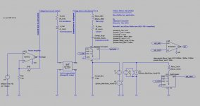
I tried to transfer this onto LTspiceIV.
Without second-order effects.
Here are some suggestions.
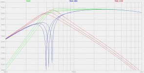
It seems to work.
I wanted to make this simulation compatible with the closed box case.
Therefore, I have kept Cab (the box compliance) inside the loudspeaker coil loop, instead of moving Cab into the vent inductance loop like W. M. Leach, Jr. did.
I wanted to have all LTspiceIV circuit elements having their values equal to their physical values without any scale factor.
The box compliance value on the LTspiceIV schematic is the box compliance seen by the woofer. This compliance comes in series with the driver suspension compliance.
The suspension compliance equals 214µm/N.
The box compliance seen by the woofer equals 170µm/N.
As a consequence if you close the vent, and if you try moving the woofer membrane by 1 millimeter, you will need to apply a force equal to :
0.001 Newton divided by the suspension compliance (= 4.67 Newton)
plus
0.001 Newton divided by the equivalent box compliance (= 5.88 Newton)
total
10.55 Newton
The vent mass value on the LTspiceIV schematic is the actual air mass contained into the vent volume. Physically, this air mass resonates with the box volume according to the Helmholtz law. The Helmholtz law can be described as a spring-mass system with almost no damping. The spring effect comes from the box volume, hence compliance SEEN BY THE VENT CROSS-SECTION AREA. The mass effect comes from the air mass contained into the vent volume.
Most of the time, the vent cross-surface area is much smaller than the driver membrane surface. The box compliance perceived by the vent cross-surface area will therefore be much higher (= easier to move) than the box compliance perceived by the driver membrane. The compliance amplification factor perceived by the vent equals the ratio of the two surfaces : driver membrane surface / vent cross-section area.
Thus, and this is the vicious trick, on the LTspiceIV schematic, we need to represent the fact that the box compliance gets perceived by the vent cross-section (and mass) as an amplified compliance.
Consider now a box compliance equal to zero. This means that the driver gets connected to the vent, without any intermediate box. You then realize that the same amplification will shows regarding the speed. If you press the woofer 1 millimeter, the air in the vent will move 1 millimeter times the amplification factor defined by the ratio of the two surfaces.
Looking to the LTspiceIV schematic, we realize that any current stolen by the inductance representing the vent, is the air speed into the vent.
Therefore if there is 1 milliamp stolen from the Compl_Box capacitor, physically, there must be 1 milliamp times the amplification factor inside the inductance representing the vent.
Now we understand the why and how of the chain made of V1, H1 and G1. This chain replaces a current multiplier. There is no current multiplier (current controlled current source) in LTspiceIV. I needed to build one using an ammeter (V1) followed by a voltage-controlled voltage source (VCVS) followed by a voltage-controlled current source (VCCS). With an amplification factor equal to the ratio of the surfaces.
At this stage we may feel happy, having implemented the vent air speed gain caused by the surface ratio. We now need to respect energy considerations. Having articifially boosted the current in the vent inductance by a certain factor, we need to artificially reduce the stimulation voltage accordingly. This is done by multiplying the voltage developping on the coil, by the same factor, then transferring this multiplied voltage back to the cause. This is the role of E1, a voltage-controlled voltage source. This way, the energy gets balanced. Yes, indeed there is a current amplification in the process, but the back-EMF generated by the inductance gets multiplied by the same facor, and this provokes a negative feedback the way the circuit is laid out. I have no better explaination.
We have not dealt yet with the initial idea of the vent seeing an amplified compliance. Is our circuit producing this feature now ? The meaning of an "amplified compliance" is that if the vent cross-section area develops a force (like an inertia force), the whole vent cross-section will move more easy than the driver membrane because the vent cross-section area is much smaller than the driver membrane surface.
A mechanical force on the vent cross-section translates into a voltage appearing at the input of E1. This voltage is multiplied by E1 and transferred across the capacitor representing the box compliance. The V1 voltage source being equal to zero by definition, this amplified voltage will equal the voltage present on the capacitor representing the box compliance. This equilibrium condition will be reached thanks to additional current starting to flow in the system, with G1 providing the current amplification hence speed amplification hence ease of move. I have no better explaination.
I would like to know if this modelization is viable.
Of course, neglecting the second-orders effects.
Steph
Page 557
Engineering Reports - "Electroacoustic design with Spice" - By W. M. Leach, Jr.
It contains a very interesting Spice simulation.
This is probably the mother of all bass-reflex speaker design softwares.
Worth reading it !
Here is a link : http://users.ece.gatech.edu/mleach/papers/spice_electro.pdf
More here : Dr. Leach's Refereed Papers.
I tried to transfer this onto LTspiceIV.
Without second-order effects.
Here are some suggestions.
It seems to work.
I wanted to make this simulation compatible with the closed box case.
Therefore, I have kept Cab (the box compliance) inside the loudspeaker coil loop, instead of moving Cab into the vent inductance loop like W. M. Leach, Jr. did.
I wanted to have all LTspiceIV circuit elements having their values equal to their physical values without any scale factor.
The box compliance value on the LTspiceIV schematic is the box compliance seen by the woofer. This compliance comes in series with the driver suspension compliance.
The suspension compliance equals 214µm/N.
The box compliance seen by the woofer equals 170µm/N.
As a consequence if you close the vent, and if you try moving the woofer membrane by 1 millimeter, you will need to apply a force equal to :
0.001 Newton divided by the suspension compliance (= 4.67 Newton)
plus
0.001 Newton divided by the equivalent box compliance (= 5.88 Newton)
total
10.55 Newton
The vent mass value on the LTspiceIV schematic is the actual air mass contained into the vent volume. Physically, this air mass resonates with the box volume according to the Helmholtz law. The Helmholtz law can be described as a spring-mass system with almost no damping. The spring effect comes from the box volume, hence compliance SEEN BY THE VENT CROSS-SECTION AREA. The mass effect comes from the air mass contained into the vent volume.
Most of the time, the vent cross-surface area is much smaller than the driver membrane surface. The box compliance perceived by the vent cross-surface area will therefore be much higher (= easier to move) than the box compliance perceived by the driver membrane. The compliance amplification factor perceived by the vent equals the ratio of the two surfaces : driver membrane surface / vent cross-section area.
Thus, and this is the vicious trick, on the LTspiceIV schematic, we need to represent the fact that the box compliance gets perceived by the vent cross-section (and mass) as an amplified compliance.
Consider now a box compliance equal to zero. This means that the driver gets connected to the vent, without any intermediate box. You then realize that the same amplification will shows regarding the speed. If you press the woofer 1 millimeter, the air in the vent will move 1 millimeter times the amplification factor defined by the ratio of the two surfaces.
Looking to the LTspiceIV schematic, we realize that any current stolen by the inductance representing the vent, is the air speed into the vent.
Therefore if there is 1 milliamp stolen from the Compl_Box capacitor, physically, there must be 1 milliamp times the amplification factor inside the inductance representing the vent.
Now we understand the why and how of the chain made of V1, H1 and G1. This chain replaces a current multiplier. There is no current multiplier (current controlled current source) in LTspiceIV. I needed to build one using an ammeter (V1) followed by a voltage-controlled voltage source (VCVS) followed by a voltage-controlled current source (VCCS). With an amplification factor equal to the ratio of the surfaces.
At this stage we may feel happy, having implemented the vent air speed gain caused by the surface ratio. We now need to respect energy considerations. Having articifially boosted the current in the vent inductance by a certain factor, we need to artificially reduce the stimulation voltage accordingly. This is done by multiplying the voltage developping on the coil, by the same factor, then transferring this multiplied voltage back to the cause. This is the role of E1, a voltage-controlled voltage source. This way, the energy gets balanced. Yes, indeed there is a current amplification in the process, but the back-EMF generated by the inductance gets multiplied by the same facor, and this provokes a negative feedback the way the circuit is laid out. I have no better explaination.
We have not dealt yet with the initial idea of the vent seeing an amplified compliance. Is our circuit producing this feature now ? The meaning of an "amplified compliance" is that if the vent cross-section area develops a force (like an inertia force), the whole vent cross-section will move more easy than the driver membrane because the vent cross-section area is much smaller than the driver membrane surface.
A mechanical force on the vent cross-section translates into a voltage appearing at the input of E1. This voltage is multiplied by E1 and transferred across the capacitor representing the box compliance. The V1 voltage source being equal to zero by definition, this amplified voltage will equal the voltage present on the capacitor representing the box compliance. This equilibrium condition will be reached thanks to additional current starting to flow in the system, with G1 providing the current amplification hence speed amplification hence ease of move. I have no better explaination.
I would like to know if this modelization is viable.
Of course, neglecting the second-orders effects.
Steph
Attachments

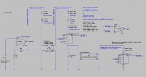
Last edited:
Now with a DC_Transformer subcircuit hiding some complexity.
Attachments


Port Design & Modeling
While it would take more time than I am willing to spend here, to revisit the subject of enclosure modeling and answer your question accurately, the following comments and information may be helpful.
1) Volume displacement [VD] in the port is twice that of the driver and is independent of duct cross section. This limit, of course, is approached as signal frequency nears system resonance and driver [VD] approaches zero.
2) In modern designs, the ports may be tapered and streamlined to avoid air flow turbulence. An extreme example of this is may be found in reflexed ports used in the not so new Bose 901 design.
3) As your issues address port modeling (and design), you may want to study the following AES articles on the subject if you have not already done so. Since I did my research, there are probably newer articles published that you may want to study as well.
Regards,
WHG
File: AESJ050-0019.pdf
Title: Maximizing Performance from Loudspeaker Ports
Author: Salvatti, Alex
Affiliation: JBL Professional, Northridge, California
Author: Button, Doug
Affiliation: JBL Professional, Northridge, California
Author: Devantier, Alan
Affiliation: Infinity Systems, Northridge, California
Publication: AES-P, No. 4855, Cnv. 105, Aug-1998
E-Lib.: (CD aes14) /pp9798/pp9809/4745.pdf
Publication: AES-J, Vol. 50, No. 1, pp. 19-45, Dec-2001
E-Lib.: (CD aes19) /jrnl2002/2002/0019.pdf
Abstract: There is a current trend in the marketplace for loudspeaker ports to have a more aerodynamic appearance. This may be as much for appearance as for performance reasons. However, the sharp discontinuity at the end of a traditional port does create turbulence at high drive levels as air is drawn into the port. As well, the axial cross-sectional shape of the port can have an influence on the turbulence generated on the air as it exits the port.
Abstract: Ports altered to provide a more aerodynamic shape to minimize turbulence for inlet and exit air streams show performance improvements in efficiency, compression, maximum output and distortion reduction and will be outlined in this paper. The ideal shapes for high velocity inlet and exit air streams are different and the best solution is one that balances both. Additionally, turbulence is actually preferred in matters of cooling the box through heat exchange via the air in the port.
File: AESP4661.pdf
Title: Reduction of Bass-Reflex Port Nonlinearities by Optimizing the Port Geometry
Author: Roozen, N. B.
Affiliation: Philips Research Labs, Eindhoven, The Netherlands
Author: Vael, J. E. M.
Affiliation: Philips Research Labs, Eindhoven, The Netherlands
Author: Nieuwendijk, J. A. M.
Affiliation: Philips ASA Labs, Eindhoven, The Netherlands
Publication: AES-P, No. 4661, Cnv. 104, Apr-1998
E-Lib.: (CD aes14) /pp9798/pp9805/4551.pdf
Abstract: Bass-reflex ports are used to enhance the bass reproduction of loudspeakers. However, at higher output levels, the bass-reflex port nonlinearities, specifically the unsteady separation of the acoustic flow, can lead to blowing sounds and acoustic losses. Calculations and measurements are presented for a number of port geometries. The effect of rounding the port terminations and the effect of converging-diverging ports on the production of blowing sounds are investigated.
Abstract: It appears that the intensity of the unsteady separation of the acoustic flow, as well as the radiation efficiency of the port and the quality factor of the port resonances, altogether determine the level of blowing noise. Maximum reduction of the blowing sounds and acoustic losses is obtained by using a port contour geometry that slowly diverges from the center towards both port ends and is rounded with curvature radii that are not too large at both port terminations.
File: AESP3999.pdf
Title: The Nonlinear Behavior of Reflex Parts
Author: Backman, Juha
Affiliation: Nokia Mobile Phnes, Salo, Finland
Publication: AES-P, No. 3999, Cnv. 98, Jan-1995
E-Lib.: (CD aes13) /pp9496/pp9502/3959.pdf
Abstract: The results of an experimental study of the nonlinear behavior of reflex ports of various shapes are presented. The parameters that are compared between the ports include noise, harmonic distortion, and flow resistance. The result is that careful design yields significant improvements in the dynamic range, however, relatively small irregularities can increase the nonlinearity greatly.
File: AESP4523.pdf
Title: Loudspeaker Ports
Author: Vanderkooy, John
Affiliation: University of Waterloo, Waterloo, Ontario, Canada
Publication: AES-P, No. 4523, Cnv. 103, Aug-1997
E-Lib.: (CD aes14) /pp9798/pp9709/4413.pdf
Abstract: The demand for high-level low-frequency sound in a cinema and home theater audio systems, and the desire for compact subwoofers, is the motivation behind the work. Tapered ports were believed to perform better than simple ones, and this study sets out to measure and analyze such ports and assess their performance. A model of an acoustic port of varying cross-section is presented.
Abstract: Acoustic ports of various shapes are studied to show their behavior at a range of levels. It is found that flared ends do help, but at high levels, some losses and distortion remain. A gently-tapered port shows better behavior.
File: AESP4748.pdf
Title: Nonlinearities in Loudspeaker Ports
Author: Vanderkooy, John
Publication: AES-P, No. 4748, Cnv. 104, Apr-1998
E-Lib.: (CD aes14) /pp9798/pp9805/4638.pdf
Abstract: The increasing demand for high SPL at low frequencies has prompted the study of nonlinearities in loudspeaker ports. At high levels, ports produce jets of air, display acoustic compression, loss and distortion, generate turbulence noise, and rectify pressure fluctuations. These phenomena are measured and analyzed. A simplified nonlinear model of a port is presented. Flared ends and gentle tapering help somewhat. The low-level linear acoustic characteristics of ports of varying cross-section are analyzed.
Abstract: The velocity profiles of ports are measured, and a new theory for this and the associated nearfield pressure is presented, which contradicts the usual "piston-in-a-baffle" approach.
File: ASAJ104-1914.pdf
[094] Title: Vortex Sound in Bass-Reflex Ports of Loudspeakers. Part I. Observation of Response to Harmonic Excitation and Remedial Measures
Author: N. Bert Roozen
Affiliation: Philips Research Labs, Eindhoven, The Netherlands
Author: Marije Bockholts
Affiliation: Eindhoven University of Technology, Eindhoven, The Netherlands
Author: Pascal van Eck
Affiliation: Eindhoven University of Technology, Eindhoven, The Netherlands
Author: A. Hirschberg
Affiliation: Eindhoven University of Technology, Eindhoven, The Netherlands
Publication: ASA-J, Vol. 104, No. 4 (Oct-1998), pp. 1914-1918, DOI: 10.1121/1.423760
Abstract: At high sound pressure levels a bass-reflex port produces blowing sounds, especially in the case of small loudspeaker boxes with narrow bass-reflex ports. The blowing sounds are caused by vortex shedding of the acoustic flow at the end of the port at high flow velocities. It has been found that acoustic standing waves in the longitudinal direction of the port are excited in a pulsatile manner by the periodically generated vortices.
Abstract: This is demonstrated by time history measurements of the blowing sounds of a loudspeaker system with a bass-reflex port driven by a harmonic signal. Broadband turbulence sound appears to be weaker than these deterministic sounds.
Abstract: It has been found that, near the 1-kHz port resonance frequency, the power level of the blowing sounds can be reduced by 8 dB by using a port cross section that diverges gradually toward both port ends with a slope angle at the port ends of about 6°, and rounding the edges at both port ends.
File: ASAJ104-1919.pdf
[095] Title: Vortex Sound in Bass-Reflex Ports of Loudspeakers. Part II. A Method to Estimate the Point of Separation
Author: N. Bert Roozen
Affiliation: Philips Research Labs, Eindhoven, The Netherlands
Author: Marije Bockholts
Affiliation: Eindhoven University of Technology, Eindhoven, The Netherlands
Author: Pascal van Eck
Affiliation: Eindhoven University of Technology, Eindhoven, The Netherlands
Author: A. Hirschberg
Affiliation: Eindhoven University of Technology, Eindhoven, The Netherlands
Publication: ASA-J, Vol. 104, No. 4 (Oct-1998), pp. 1919-1924 , DOI: 10.1121/1.423762
Abstract: In part I of this paper, the vortex shedding that may occur in a bass-reflex port of a loudspeaker system was discussed. At the Helmholtz frequency of the bass-reflex port, air is pumped in and out at rather high velocities, vortex shedding occurs at the end of the port, and blowing sounds are generated. It was explained that the key in the design of a port with a minimum of blowing sounds is the point of flow separation from the wall at which vortices are formed.
Abstract: This paper presents a method for estimating the point of separation for an unsteady flow like the flow through a bass-reflex port. Assuming that the flow can be described by a potential flow up to the point where flow separation occurs, it was found that the point of separation can be estimated on the basis of measurement of the sound pressure inside the loudspeaker box and measurement of the sound pressure at a distance of 1 m from the port exit.
Abstract: Application of the proposed technique to a cylindrical port with rounded edges at both port ends revealed that the point of separation is determined by the particle displacement rather than by the particle velocity. It was also found that a good indicator of the onset of severe vortex shedding is the Strouhal number based on the radius of curvature of the port edges.
Title: The Acoustic Reactance of Small Circular Orifaces
Author: R.H. Bolt
Author: S. Labate
Author: U. Ingard
Publication: ASA-J, Vol. 21, No. 2, Mar-1949
Abstract: A precise experimental study of the reactive component of the complex impedance of small circular orifices has been made for a number of orifices varying in diameter from 2 cm down to 0.357 cm, with diameter/ thickness ratios from 4 to 40, over the frequency range from 200 to 1000 c.p.s. The measurement of the impedance is performed with a precision impedance tube.
Abstract: A theoretical correction for the influence of the tube walls is applied by considering the orifice to act as a plane piston and taking into account the influence of all possible higher order modes of the tube in the neighborhood of the orifice.
Abstract: Comparison between calculated and measured values of reactance shows that, as far as this quantity is concerned, the assumption that the orifice acts like a plane piston appears valid for radii equal to or greater than 1 cm for "thin" orifices within the range of variables specified above. For orifices of radii less than 1 cm, however, a modification of the radius is necessary to make the classical theoretical equation for orifice reactance fit the measured data.
Abstract: The observations and analyses reported here are restricted to wave lengths much greater than the hole diameter and to the low velocity region where reactance is independent of particle velocity.
Title: Exact Solutions for Sound Radiation from a Circular Duct
Publication: NASA, Ames Research Center, Type: PDF, Size: 262 kb
URL: http://jit.arc.nasa.gov/atrs/97/cho/976769/976769_cho.pdf
Author: Y. C. Cho
K. Uno Ingard
Abstract: This paper presents a method of evaluation of Wiener-Hopf technique solutions for sound radiation from an unflanged circular duct with
File: AESJ050-0019
Title: Maximizing Performance from Loudspeaker Ports
Author: Alex Salvatti
Author: Allan Devantier
Author: Doug J. Button 19
Publication: AES-J, Vol. 50, No.1, p. 19 (Jan-2002)
Abstract: The low-frequency performance of a loudspeaker is significantly enhanced by the use of tapered ports, but there are numerous trade-offs involving the size of the port and the input and output tapers. Design issues include the effectiveness of heat transfer, amount of turbulence created, air velocity, smoothness of the taper, symmetry of the two tapers, effective mass in the port, and the contribution to the frequency response. Suggested design rules are based on extensive empirical studies.
- Status
- Not open for further replies.