Unfortunately (or fortunately) when you move off axis, a lot of these bands will have affected the frequency response negatively as well. The frequency response of a total loudspeaker system depends on the on-axis response of the driver, but also on the off-axis response of the driver which varies, baffle step, diffraction etc etc etc. You are tweaking ONE signal that goes to the drive unit, so everything you do to get that on-axis response flat is also going to affect the aspects of the total system response. At the very least this requires knowing how the off axis frequency responses look like at small increments, which parts are driver related, which are cabinet related, which ones respond well to EQ, which don't etc etc etc.
Which is why some of the most "digital" audio designers I know seem to talk like they are "full moon virgin elves snake oil ritual audiofools" in the sense that they insist to filter less rather than more, only filter peaks that show up on off-axis curves as well, never boost a dip, start with a good driver anyway, select the best angle with the smoothest frequency response and optimise for that angle and dictate that is the mandatory listening angle etc etc etc.
The rules never really changed going from analogue passive to active DSP. We just bang into the consequences of our choices a lot sooner with DSP. 😂😂😂
I think anyone should as much DSP as they like, and I certainly look for drivers that have a frequency response that allows enthusiastic DSP. But I also have experienced that the most elaborate filtering is usually not the best. And so do very DSP minded professionals.
Otherwise, I'm with you, if loudspeaker building is your hobby, and a DSP is available, I would always use the DSP option for ease, speed and control.

Hi
I am planning about same project with CHP-90. but the results of simulator and real measurement differ greatly abowe 500hz.
The picture shows that you have done real serious measunents. Is it possible to see some unsmoothed graphics
Best wishe hpu
Ps
My problem Is that the box inside resonances leak out thru the hole and element.
Hi
I am planning about same project with CHP-90. but the results of simulator and real measurement differ greatly abowe 500hz.
The picture shows that you have done real serious measunents. Is it possible to see some unsmoothed graphics
Best wishe hpu
Ps
My problem Is that the box inside resonances leak out thru the hole and element.
Hi,
Scale is usually the bigger difference. Baffle will then change the rest.
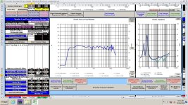
Here's the anechoic in-baffle response at standard 5db scale with zero smoothing applied:
Here's the published frequency response from Mark Audio on this driver:
Let's compare, theirs is free air, mine is on a large baffle, flush mounted, but the baffle changes things.
Notice Mark Audio's scale is 10db. This makes it appear flatter. Most use a standard of 5db. So, let's scale to the same as them. Here's my measurement using the same scale as the publication (0db to 100db). Note, they go out to 30khz, I went to 20khz. Keep that in mind, so only look to 20khz on their measurement.
Let's compare.
Spike/hump at 500~600hz, present just like in published version.
Spike/hump at 1khz range, present just like in published version.
Significant spike at 4.2khz, present but smaller in published version.
Significant spike at 6.5khz, present but smaller in published version.
Significant humping at 8khz to 15khz and a big spike right on 11.6khz range, present but less amplitude in the published version.
So it's not that different. I just have more amplitude on the same spikes, because mine is on a baffle and they get +6db to their range.
Very best,
It's also my experience that Mark Audio specs are very accurate, altough generalised and smoothed. They don't do like some other manufacturors make spec sheets that are far from reality or so.
When I measured the Mark Audio drivers on the DATS system, the cold out of the box T&S values were much closer to published than other drivers I've measured. It was nice.
Very best,
Just killing some time here.
Looks good! What did you end up doing?
Very best,
Details are on the left side when you click on the attachment. Totally impractical from a cost standpoint.
I am curious about your measurements, and this drivers ragged response. I measure my drivers gated to 4.6ms or so, and most are much smoother. I've been told that gating smooths the measurement. My indoor REW measurements show a response down to about 250hz. On different resolution settings, some don't change much at all. I use the short sweep, but tried the longer ones a few months back, and don't recall any difference.
I am curious about your measurements, and this drivers ragged response. I measure my drivers gated to 4.6ms or so, and most are much smoother. I've been told that gating smooths the measurement. My indoor REW measurements show a response down to about 250hz. On different resolution settings, some don't change much at all. I use the short sweep, but tried the longer ones a few months back, and don't recall any difference.
but the results of simulator and real measurement differ greatly abowe 500hz.
Not surprising, simulators only simulatre low frequencies, it doesn’t give youany indication of response above 500 Hz,
dave
Just following up, here's how it played out.
I took my anechoic measurements above and put them in virtuixcad and played with a contour filter. Just basic baffle step and a cap to lower the upper region. It seemed simple enough, no notches, etc, to keep it simple and inexpensive.
Here's the circuit simplified.

What the filter is expected to do to the response as an "EQ":

Predicted response & impedance:

I thought about adding another resistor, 15~16ohm, as seen here to further flatten out impedance, if it actually behaves that way:

Predicted result would be:

Then I built a temporary contour filter as above, but without that 2nd resistor (the 15ohm one). I may add that. I will test further.
Here's the initial results.
These measurements are not anechonic, just in room at the listening position, just a quick dirty metric to see if the filter is going the right direction at all or not. This is not gated, or corrected at all. I will do that at another time when I finalize the filter.
Red is the raw response with no EQ and just straight from an amp.
Blue is with the contour filter in place (the first one above) to see if it handles as expected.
It worked well. It sounds great. It's much flatter and the peak above 12khz is calmed way down. Now when its turned to listening levels it's flat sounding and has good extension to 40hz and sounds as I would expect. So, this may be the final version of this filter. Unless anyone can suggest a way to do this even better. But so far, this is great, and its super duper simple.

Very best,
I took my anechoic measurements above and put them in virtuixcad and played with a contour filter. Just basic baffle step and a cap to lower the upper region. It seemed simple enough, no notches, etc, to keep it simple and inexpensive.
Here's the circuit simplified.
What the filter is expected to do to the response as an "EQ":
Predicted response & impedance:
I thought about adding another resistor, 15~16ohm, as seen here to further flatten out impedance, if it actually behaves that way:
Predicted result would be:
Then I built a temporary contour filter as above, but without that 2nd resistor (the 15ohm one). I may add that. I will test further.
Here's the initial results.
These measurements are not anechonic, just in room at the listening position, just a quick dirty metric to see if the filter is going the right direction at all or not. This is not gated, or corrected at all. I will do that at another time when I finalize the filter.
Red is the raw response with no EQ and just straight from an amp.
Blue is with the contour filter in place (the first one above) to see if it handles as expected.
It worked well. It sounds great. It's much flatter and the peak above 12khz is calmed way down. Now when its turned to listening levels it's flat sounding and has good extension to 40hz and sounds as I would expect. So, this may be the final version of this filter. Unless anyone can suggest a way to do this even better. But so far, this is great, and its super duper simple.
Very best,
The added 15 ohm resistor will get hot as its across the amplifier without a highpass. Please attach it in series with the 10uF across the driver.
All you did by adding it as shown was reduce output potential by burning off wattage as heat.
Which resistor are you referring to? The first 10ohm with the inductor? Or that 2nd resistor, 16ohm, in the 2nd iteration?
Edit: sorry duh you stated the 15ohm. That one is not currently in the filter. That was just another iteration looking at impedance. It didn't change the response so I didn't include it. It's currently not in there, and if it's not helpful, it won't go in. I'll keep it super simple with 3 components currently. Thanks for pointing that out.
Very best,
Last edited:
Hi,
I have a partial build log here, that is shorter, here on DIYAudio:
Thanks! Yea, it was around 450~460g into less than 1 ft^3 since the lower chamber was not stuffed with polyfil. Still, without measurements, I wasn't hearing anything weird.
Thanks! It was definitely different for me, just trying different things to step up my finish game. Learned a bunch on this one.
My complete build log with every little detail is here on AVS:
https://www.avsforum.com/threads/markaudio-chp-90-bass-reflex-monitors-live-oak-slabs.3309193/
I designed it larger than was needed for the tuning, I over sized so I could get more of a peak potentially at its tuned value. This is not necessary and ultimately didn't work exactly as expected, but still worked out well. Bottom line, its a 1 ft^3 net internal volume tuned too low for what it should have been. Its Fs is 48.5hz. I should have tuned closer to that. But I pushed down to 40hz to see if I could and while it works, its not optimal. Up to you how you want to do things. The port length entirely depends on the volume and tuning and the type of port you implement (and where).
See my AVS build log for every little detail and if you have questions I'm happy to help out. Not a perfect build, but learned a lot through doing it.
Now I'm going back and doing a contour filter to smooth it out without EQ.
Very best,
I have a partial build log here, that is shorter, here on DIYAudio:
Very pretty!!!
Look like the polyfluff could use more teasinmg. And next time look for plug with plastic nuts (less metal)
dave
Thanks! Yea, it was around 450~460g into less than 1 ft^3 since the lower chamber was not stuffed with polyfil. Still, without measurements, I wasn't hearing anything weird.
Great work! Super creative approach to a box speaker.
Thanks! It was definitely different for me, just trying different things to step up my finish game. Learned a bunch on this one.
How do you apply the Deep Pour Epoxy? Just pour it on and let the excess run off...
My complete build log with every little detail is here on AVS:
https://www.avsforum.com/threads/markaudio-chp-90-bass-reflex-monitors-live-oak-slabs.3309193/
I designed it larger than was needed for the tuning, I over sized so I could get more of a peak potentially at its tuned value. This is not necessary and ultimately didn't work exactly as expected, but still worked out well. Bottom line, its a 1 ft^3 net internal volume tuned too low for what it should have been. Its Fs is 48.5hz. I should have tuned closer to that. But I pushed down to 40hz to see if I could and while it works, its not optimal. Up to you how you want to do things. The port length entirely depends on the volume and tuning and the type of port you implement (and where).
See my AVS build log for every little detail and if you have questions I'm happy to help out. Not a perfect build, but learned a lot through doing it.
Now I'm going back and doing a contour filter to smooth it out without EQ.
Very best,
Last edited by a moderator:
Update, finished the contour filter and measured it.
Here's the simple filter I ended up doing:


Here's the filter built:


And updated measurements with this filter:


Final response, fully corrected:

The set:


Very best,
Here's the simple filter I ended up doing:
Here's the filter built:
And updated measurements with this filter:
Final response, fully corrected:
The set:
Very best,
- Home
- Loudspeakers
- Full Range
- MarkAudio CHP90 Full Range Bass Reflex Monitor, Passive Crossover Response Help